What is a mooring line?
Mooring lines generally comprise ropes, wires, chains or combination of wire and chain used to keep ships, offshore platforms and other floating vessels in position. It connects the structure either to the seabed using an anchor or the quay side using a bollard and prevents the vessel from drifting away due to loading from waves, winds and current. Offshore moorings are typically used for drilling and production platforms and their configuration depends on the water depths. For small water depths, e.g. below 300 m, a chain only line may be used but as we go deeper, the required length of the mooring line increases and it becomes hard for the vessel to support the weight of the chain. Hence a lighter alternative of a chain-wire-chain composite line is used. The line has chains at each end to be able to connect to the anchor (end on seabed) and the chain stopper (end on structure). For ultra-deep waters, a polyester rope is used in between chains to further reduce the weight.
Catenary Principle
A mooring line is just a suspended cable and so the shape it assumes is catenary shape. The weight of the suspended length of the cable translates into tension at either ends. For offshore mooring line the cable is anchored on the seabed and attached to the structure on top. If the vessel moves, the catenary shape changes there by changing the tensions in the line. The further the top end is from the anchor, the larger is the suspended length and hence the tension is larger. This increased tension acts as a restoring force (stiffness) to the motions of the structure. The lines are laid out in a symmetric pattern to provide stiffness in all directions. Also the change in tension with offset of the structure is non-linear i.e. as the structure moves farther and farther, the rate of increase in tension is larger and larger. Thus the structure remains within a region for a given environment and the footprint of the structure’s offset is called a watch circle.
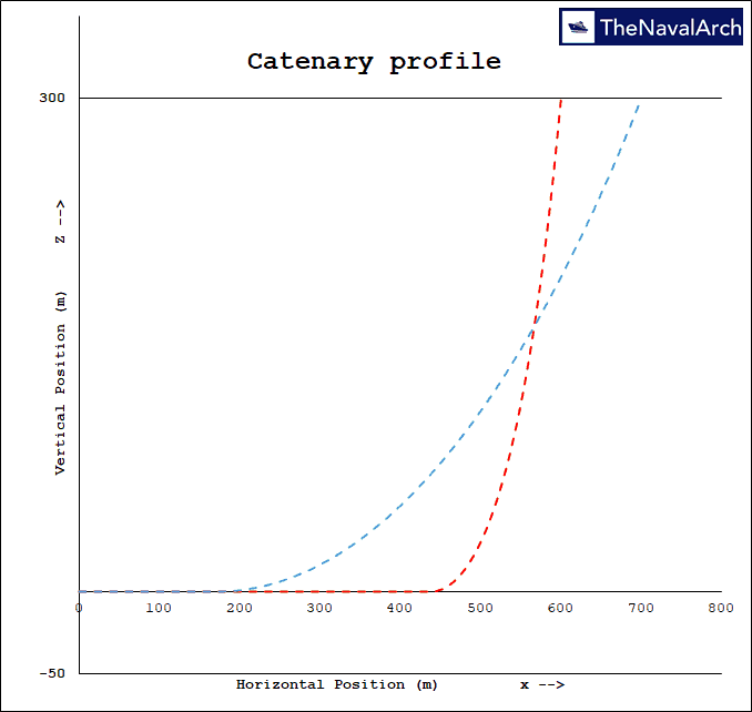 Fig. 2: Catenary profile – Mooring Line Catenary App(TNA) | 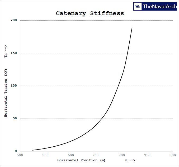 Fig. 3: Catenary Stiffness – Mooring Line Catenary App(TNA) |
it is important to understand the catenary shape in order to design the moorings and choose the right material properties of the line that will allow the structure to remain within limits of operation and also keep the loading on the line well below its breaking limit. The factor of safety associated with the design of mooring lines is defined in standards from API and DNV, but will not be discussed here.
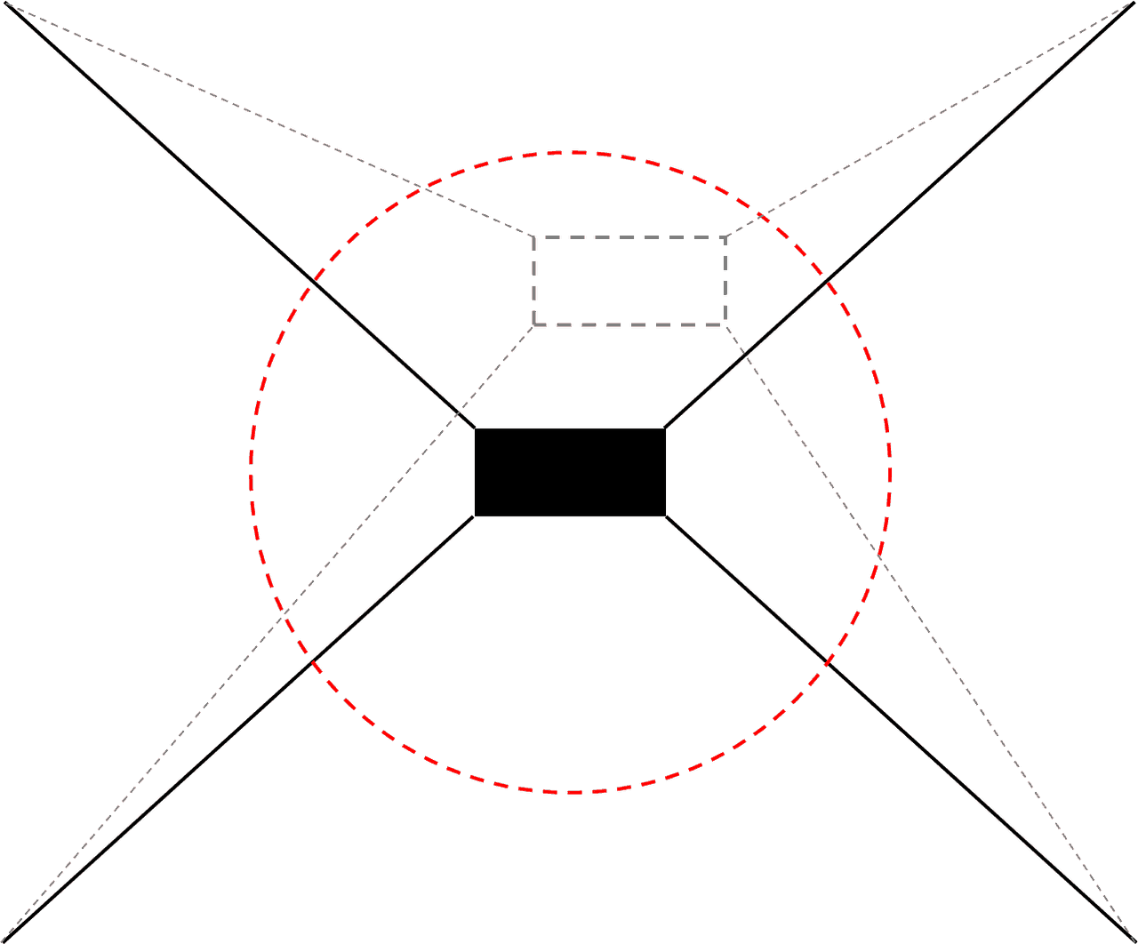
Fig. 4: Watch Circle
Catenary equation
Let’s get into the math behind a catenary shape. A cable suspended from two points will have its weight supported by the reactions at the two points. This net reaction is the same as the tension in the line at that point. The tension at any point in the line can be divided into its horizontal and vertical components.
Boundary Conditions
We will focus on offshore mooring lines and use the boundary conditions suited for this application. We will also assume that the line is non-stretchable such that the catenary effect is only due to the weight of the line. Since for an offshore mooring line, one of the ends is anchored to the seabed and if correctly designed, the line will always have a certain length on the ground, we can assume that the vertical component of the tension at the anchor is zero. At the touchdown point, where the line leaves the ground and becomes suspended, the vertical component of tension will also be zero.
Pretension
From the equations below we will see that the distance of the fairlead from the anchor and the length of the line paid out determines the tension in the line. If the vessel is assumed to be in static equilibrium without any external loads, this tension is called pretension. Pretension for a mooring system has to be chosen appropriately to achieve the desired watch circle. A lower pretension will result in lower max tensions in the line but the offsets will be large while a higher pretension will result in large max tensions with smaller offset. Hence it has to be tuned appropriately to achieve the desired performance of the mooring system while not risking damage to the line.
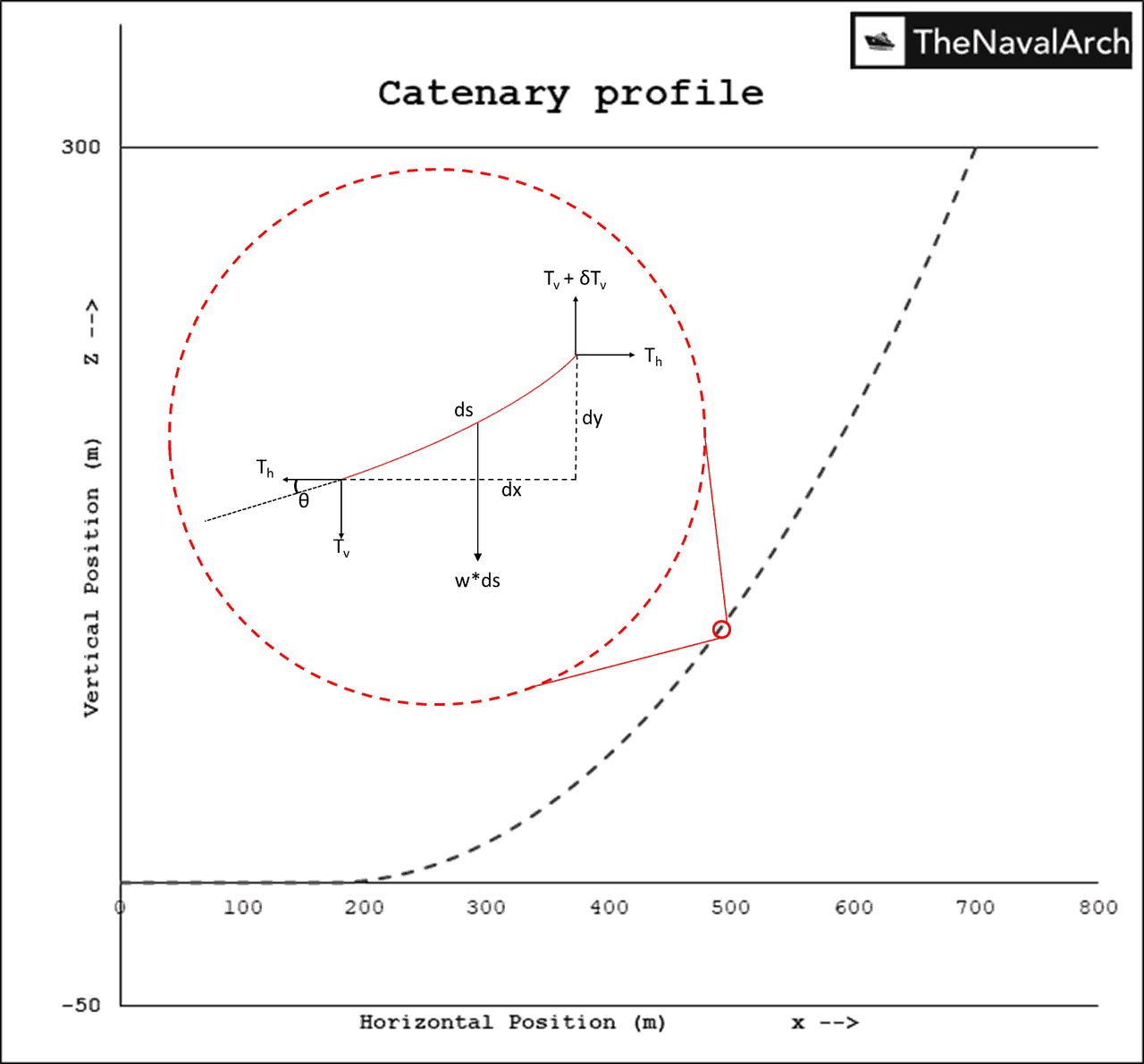
Fig. 5: Catenary profile and forces on a section
Assume a section anywhere in the suspended section of the line as show in the figure below. Each end has the tension components and the weight of the section acts vertically down wards. If the line is static, the forces should be balanced. Which means the horizontal tensions (Th) at the two ends are equal while the vertical tension (Tv) at the top end is larger than the vertical tension at the lower end by the weight of the section. Below equations show the force balance for this section in the vertical direction.
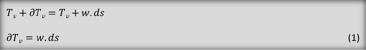
where w is the weight per unit length of the line. From Fig. 5,
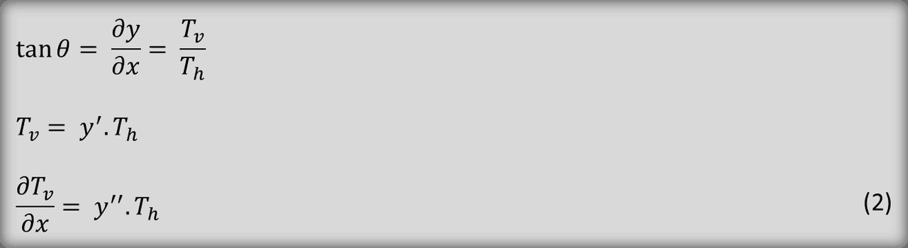
Substituting Eq. 1 in Eq. 2
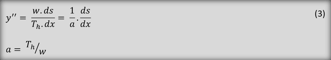
where a is known as the catenary parameter. Also, from Fig. 5,
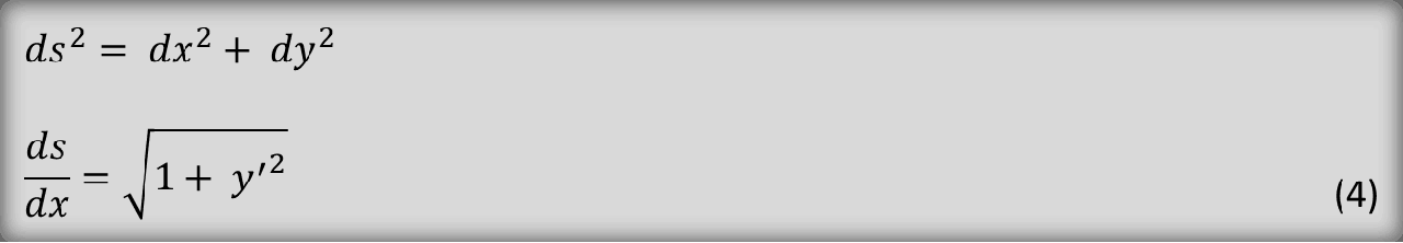
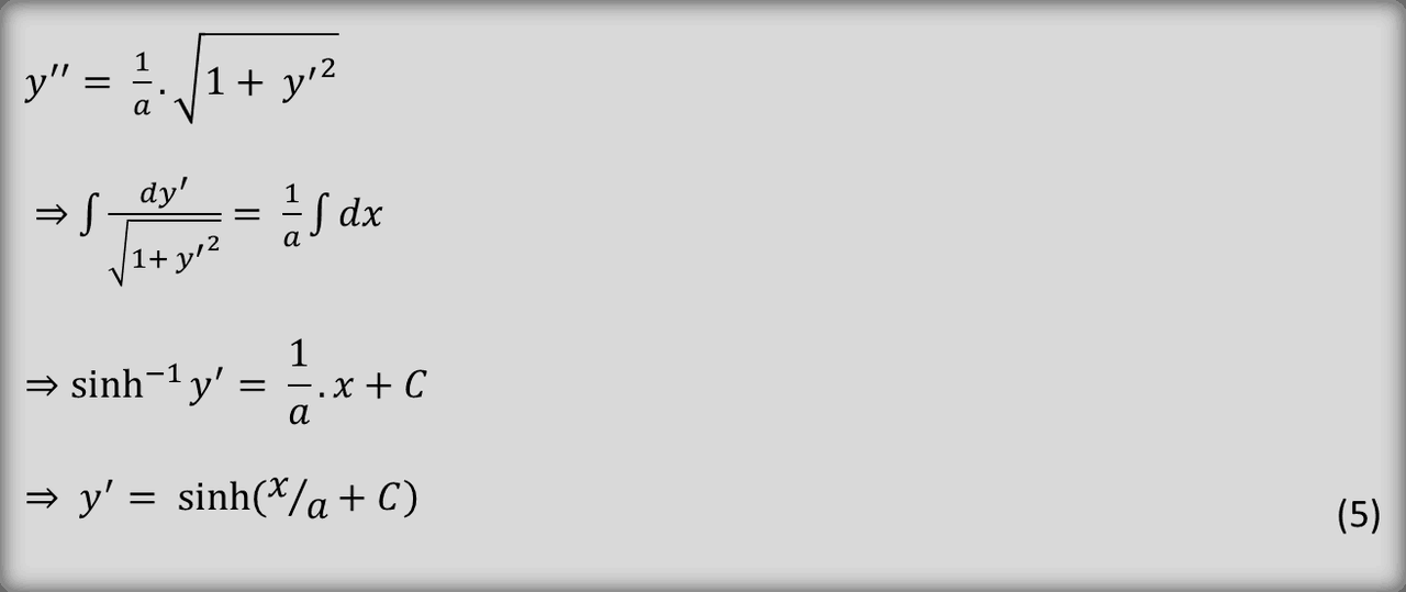
Substituting Eq. 4 in Eq. 3 and integrating we can derive the equation for the catenary shape.
If we assume the origin at the touchdown point such that the boundary condition at x = 0 are,

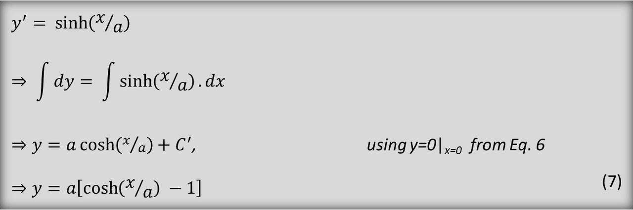
y’ here is the slope of the catenary line at horizontal position x. Since the line rests tangent to the ground at x=0, the slope of the catenary y’ is also 0. Using this condition in Eq. 5 yields C = 0. Further integrating Eq. 5 and using the boundary conditions from Eq. 6 gives the catenary shape i.e. y coordinate of the line for a given x and horizontal tension.
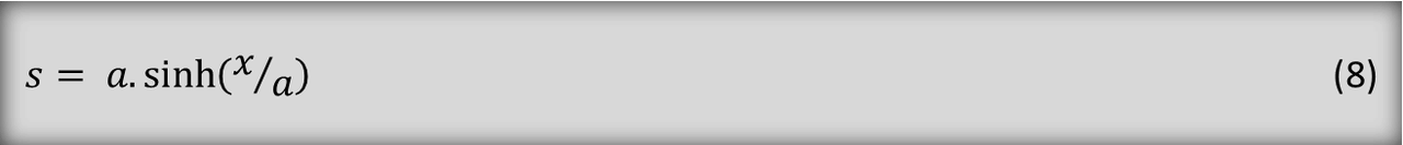
These results can be substituted back in Eq. 4 and integrated to get an expression for s or arc length for a given x.
It should be noted here that the x coordinate in the equations above are measured from the touchdown point and the vertical tension at the touchdown point will always be 0 since the equations are derived for this boundary conditions (Eq. 6).
How to solve
Lets say we have line length of 300 m, the anchor is 200 m away from the fairlead and the vertical separation between anchor and fairlead is 100 m. We start with some initial values of line length on ground and horizontal tension Th. Subtracting the line length on ground from the total length will give us the suspended length s. This can be used in Eq. 8 to get the calculated horizontal position x of the fairlead. Using this x in Eq. 7 gives us the calculated vertical position of the fairlead. If the calculated position of the fairlead is different from the required position i.e. (200, 100) from the anchor, the process has to iterated again by suitably changing the length on ground and horizontal tension. This problem of minimizing the error between calculated and target fairlead positions by changing length on ground and Th can be easily setup using an Excel Solver.
The above equations assume that the line is homogeneous i.e. the line is made of a single material like all chain or all wire. For composite lines that are combination of different line types like chain-wire-chain, each segment’s catenary equations have to be solved maintaining the continuity of the boundary conditions at the joints.
Catenary with a buoy
Simply put a buoy is just a floating device tethered to the seabed and used in several applications like
- marking specific locations in the sea, e.g. ship wreck, limits, divers
- as a light demarcation for navigation at night,
- as a measurement device with several sensors to measure, wave height, temperature etc.
- Mooring of ships
For an offshore mooring line, a buoy could be used for
- Single Point Mooring (SPM) where a surface buoy is moored to the sea bed and the vessel is tethered to the buoy using hawsers,
- or as a part of a hybrid mooring line where the buoy is attached along the line length. This is done either to change the stiffness characteristics of the line or get more clearance from nearby structures, pipelines etc.
The boundary conditions for a SPM is no different than a simple catenary but a hybrid line needs to consider additional boundary conditions and have been discussed below.
Boundary conditions at Buoy
Solving the static equilibrium condition for a mooring line with buoy is very similar to solving the catenary equations as discussed above. If we have a single buoy the line is considered to be made of two catenaries and each catenary is solved individually. Additionally, the boundary conditions at the buoy i.e. horizontal and vertical forces are also to be satisfied. Fig. 6 shows the forces at the buoy connection point. Th1 and TV1 are horizontal and vertical forces due to one segment and Th2 and TV2 are horizontal and vertical forces due to the other segment respectively. Since no external forces are considered here, Th1 and Th2 must be equal while the sum of the vertical forces, Tv1 + Tv2 should balance the nett buoyancy (Bbuoy – wbuoy) from the buoy.
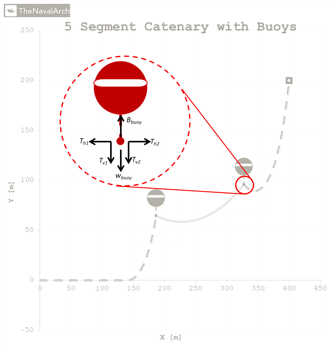
Fig. 6: Boundary conditions at a Buoy
It should be noted here that while solving for the catenary segments, not all segments will touch the ground. The above equations (Eq. 1 – 8) are derived for the boundary conditions where the segment is touching the ground such that the tangent (y’) of the segment at the ground is zero. This may not be true for the segments with buoy and the correct boundary conditions have to be used.
Conclusion
We saw in the article above how to derive the equations for a catenary shape with a length on the ground and the boundary conditions that apply if a buoy is attached to the line. the equations can be easily used to calculate the shape of the line and the tensions anywhere in the line. However, the calculations can become quite complicated as the number of segments in the line increase and if there are multiple buoys.
The Naval Arch offers two applications to solve the above equations and also includes more complex boundary conditions to solve for realistic scenarios. Both the apps offer to solve for multiple segmented line while one of them also offers including buoys along the line length. The apps are listed below with links to their product page.
Cheers
Getting the right thickness of GRP laminate for your boats
Introduction GRP laminates are widely used in the fabrication of high-speed crafts and light crafts/boats globally. GRP stands for Glass Reinforced Plastic. As the name suggests, GRP contains glass fibers embedded into a plastic resin. This gives it higher strength,...
Designing Fillet Welds for Symmetrical Joint Sections
Introduction Fillet welds are the most commonly used weld types in marine structures. A fillet weld is used when there are two pieces of metal that are joined perpendicular to each other or at an angle. In this article, we will explore how to select the right size...
Designing a stanchion/stopper for sea-fastening of deck cargo
Introduction Stanchions – a familiar term for mariners and ship designers. What are Stanchions? A stanchion is generally a vertical pipe or beam which is used to support some structural item or provide support rails on the deck. In ships, the most common type of...
Hydrogen as an alternative fuel for ships to reduce emissions
,This article first appeared in the Feb 2019 edition of Marine Engineers Review. It is being reproduced with minor edits here for the readers of TheNavalArch's blog. Introduction The world is on facing a grave environmental challenge with an increase in carbon...
Global wave statistical analysis and its use in deepwater operations
Why do we need wave analysis? For the design of offshore operations such as installation and transport of offshore structures, as well as lifecycle design of floating and fixed structures, knowledge of extreme waves as well as the probability of different sea-states...
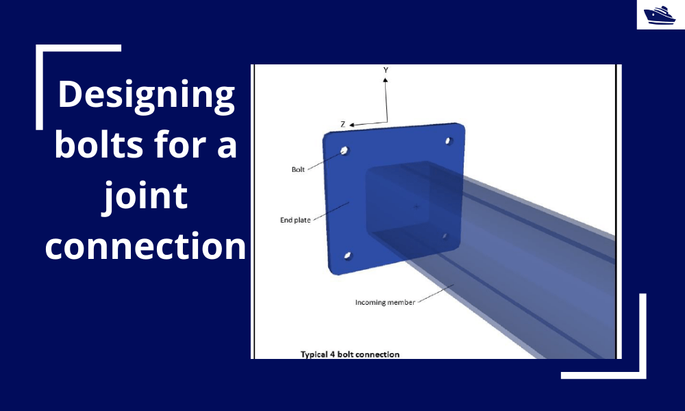
Designing bolts for a joint connection
Introduction Bolts are very commonly used fastening items and used in a variety of configurations. In this article, we will explore in-depth the design of a bolt used in connecting two members at a joint (bolted joint). We'll see what properties of the bolt are...
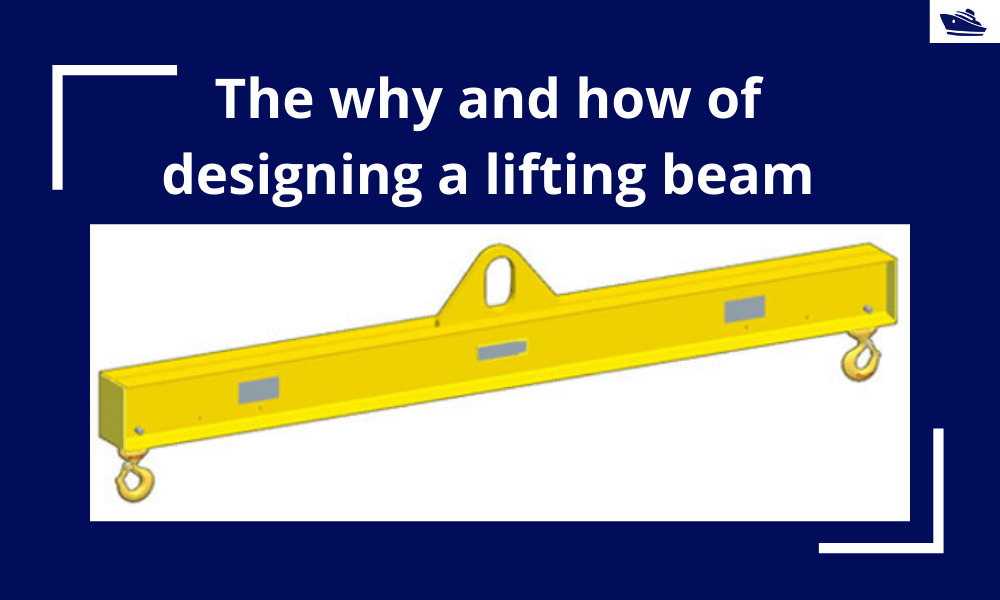
The why and how of designing a lifting beam
Lifting beams are universally applied gear used widely in various types of lifting operations, onshore and offshore. In this article, we will explore the design of a basic lifting beam and see what design checks are needed to establish the suitability of the beam for...
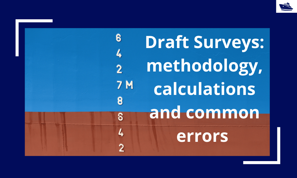
Draft Surveys: Methodology, Calculations, and common errors
Introduction Marine transport is the backbone of the global trade and reasonably can be considered to be the artery of the global manufacturing supply chain, as more than four fifths of the world merchandise trade by volume is carried by sea. Undoubtfully, the...
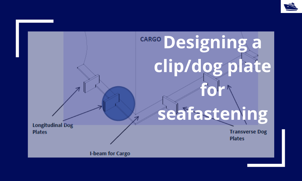
Designing a clip/dog plate for seafastening
Introduction In an earlier article, we saw how to design stoppers for seafastening. Stoppers are items that are used to contain the translation movements (longitudinal and transverse directions) of a cargo on the deck/hold of a vessel. That brings us to the question –...
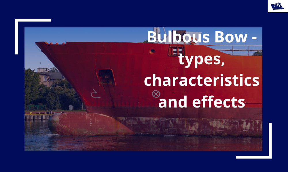
The Bulbous Bow – types, characteristics, and effects
This is Part 2 of the two-part series on Bulbous Bows. For Part 1, click here By Tamal Mukherjee, *This article originally appeared in May 2019 edition of Marine Engineers Review (India), the Journal of Institute of Marine Engineers India. It is being...

Interesting and useful for our current job