Resistance estimation for a vessel is a fundamental exercise in design of the vessel. Resistance is a property that depends on the vessel’s shape and form. A conventional ship-shaped vessel with a bulb will have completely different resistance characteristics compared to a high-speed planing vessel.
Resistance estimates are done using various methods – by hydrodynamic modeling/CFD analyses or by model testing for accurate estimates, or by using empirical relations in the preliminary design phase for a fair estimate of the resistance.
Empirical relations too vary depending on the vessel type. While Holtrop-Mennen method is the most popular one that is used for conventional ship forms (usually merchant vessels), it does not apply to high-speed hulls and planing boats.
Planing vessel resistance calculator – TheNavalArch
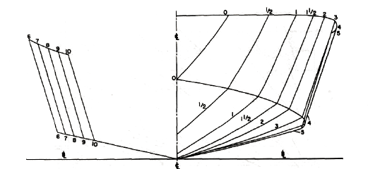
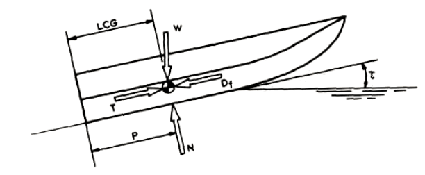
A planing vessel is distinguished form a conventional displacement vessel by the mechanism of weight support. While for a displacement vessel, the buoyancy of the vessel supports its weight, a planing vessel supports its weight by the hydrodynamic lift forces generated when the vessel moves at high speed over water. When the planing vessel is at rest or at low speeds, its weight is supported by its buoyancy, but as it moves with higher speeds, hydrodynamic lift forces are generated by the specially designed hull shape of the planing craft and these lift forces fully support the hull. In some crafts the lift and buoyancy both support the weight. A typical body plan of a planing craft is shown below:
In this article, we will look into a theoretical approach to estimating a planing craft’s performance. A number of resistance tests have been performed by Savitsky (1964) to determine formula for lift and drag of planing vessels, and empirical relations have been provided for the drag.
In this method, at equilibrium, part of the lift is generated by Buoyancy while the rest is generated as hydrodynamic lift. The important parameters of the vessel like its dimensions, speed, displacement etc are taken as inputs, and parameters like trim angle, wetted length of the keel etc. are determined. These parameters are then used to determine the resistance of the vessel.
The method and steps can be broken down into the following:
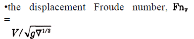
- Step 1 – Calculate the Displacement Froude number: The first parameter to be calculated is the displacement Froude number. It is defined thus
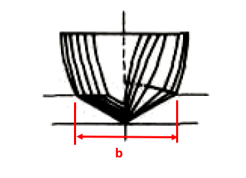
- Step 2 – Calculate the Froude number based on ‘b’: Here, ‘b’ is the maximum beam of the vessel over chine or spray strips. This is the beam of the planing area of the vessel
CV = V/√(gb)
Planing vessel resistance calculator – TheNavalArch
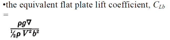
- Step 3 – Calculate the equivalent flat plate lift coefficient: This is calculated by using the formula:
- Step 4 – Calculate the lift coefficient for a finite deadrise: Depending on the deadrise angle β, the lift coefficient for a finite deadrise is calculated from the flat plate lift coefficient by using the following formula:
![]()
- Step 5 – Calculate the p/b ratio, where p = longitudinal center of gravity (LCG) of the vessel (see below)
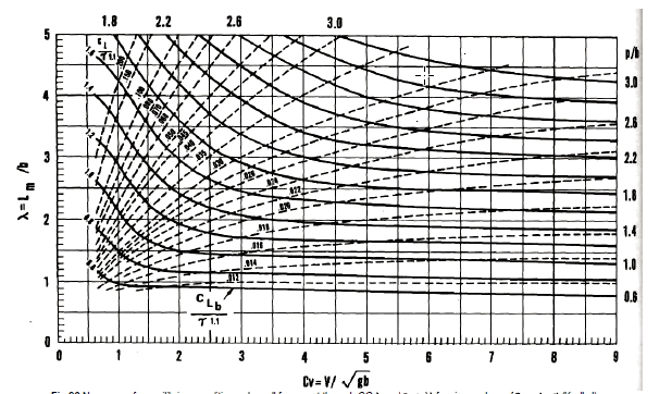
- Step 6 – Calculate the mean wetted length-beam ratio: This is the ratio λ = Lm/b, which is obtained from the Koelbel’s curves.
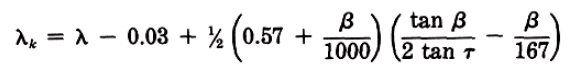
- Step 7 – Calculate the trim of the vessel in equilibrium: This is calculated by using the Savitsky formula:
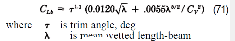
Here λ is the ratio of the mean wetted length to the beam of the planing area, i.e., Lm/b, obtained in Step 6
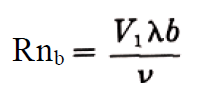
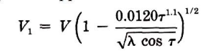
- Step 7 – Calculate the keel-wetted length ratio: This is calculated by using the formula:
- Step 8 – Check if the vessel is fully planing: If λk <= LWL/b, then it is fully planing, i.e., the bow is clear of water, else it is not. If it is fully, planing, then the method is valid, else this method is not applicable for vessels not fully planing
- Step 9 – Use the formula to calculate resistance:

W is displacement. Here, CFO is calculated from ITTC Line, using the following formula
CFO = 0.075/(log10Rn -2)2
Do check our our product Planing Vessel Resistance Calculator
References
- https://en.wikipedia.org/wiki/Planing_(boat)
- Principles of Naval Architecture Second Revision, Volume II Resistance, Propulsion and Vibration
Disclaimer: This post is not meant to be authoritative writing on the topic presented. thenavalarch bears no responsibility for the accuracy of this article, or for any incidents/losses arising due to the use of the information in this article in any operation. It is recommended to seek professional advice before executing any activity which draws on information mentioned in this post. All the figures, drawings, and pictures are property of thenavalarch except where indicated, and may not be copied or distributed without permission.
Marine Propeller Shafting and Shafting Alignment – Part 1
*****This article first appeared in July 2018 edition of Marine Engineers' Review (MER), India. We're reproducing it for the readers of our blog***** Abstract: Since 2013, Shaft Alignment Practice has undergone a change, with developments of Analysis tools. At the...
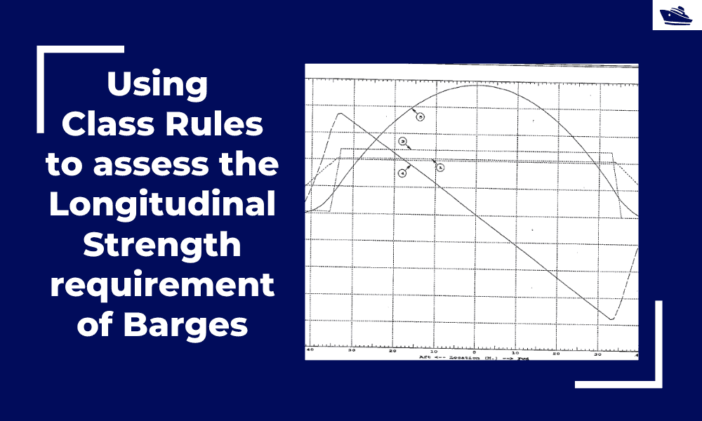
Using Class Rules to assess the Longitudinal Strength requirement of Barges
Introduction The longitudinal strength of a vessel is integral to its evaluation for a given purpose. To get an introduction to the topic, please refer to our other article https://thenavalarch.com/longitudinal-strength-ships-introduction/ In this article, we’ll see...
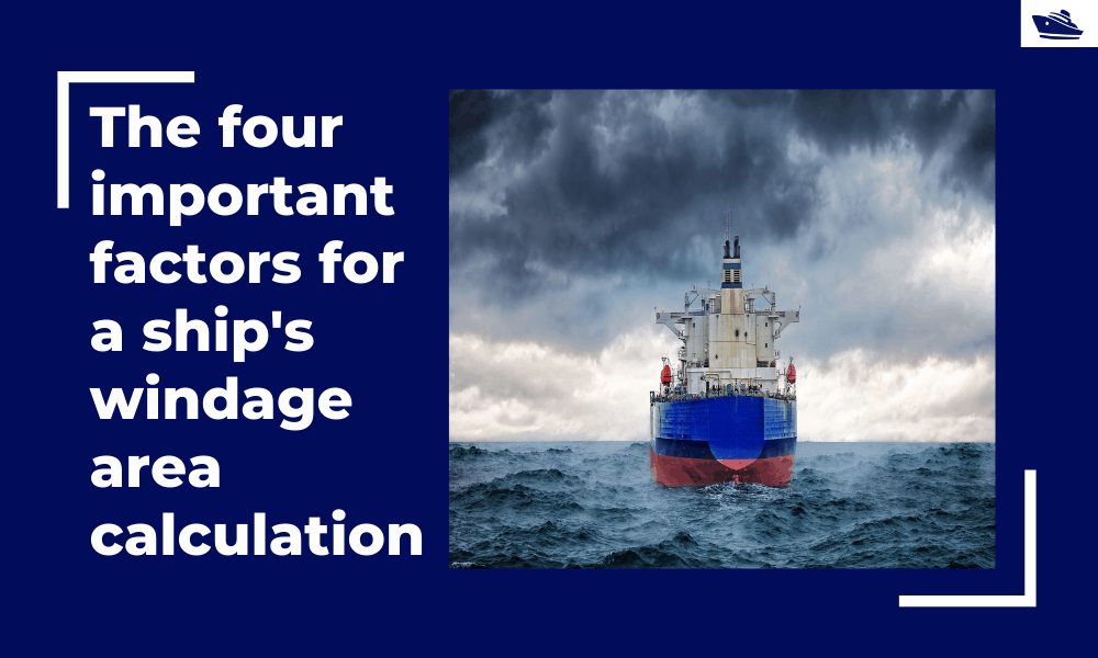
The four important factors for a ship’s windage area calculations
Introduction The windage area of a vessel or offshore structure is the area that is exposed directly to the wind. As is obvious, this is the area of all items above the waterline. This will include Part of the hull/offshore structure above the waterline...
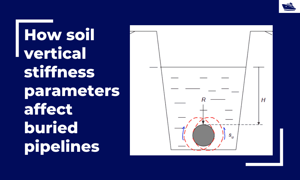
How soil vertical stiffness parameters affect buried pipelines
Introduction Pipe soil interaction is a critical subject of analysis in the field of the offshore industry. A pipe once buried in the seabed is usually in equilibrium with the surrounding soil. There are however various forces which are still in action even if the...
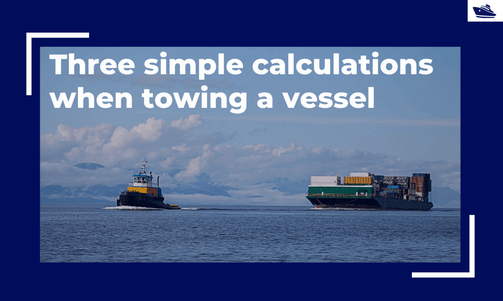
Three simple but useful calculations when towing a Vessel
In this article, we will explore three simple but useful calculations that can be used for towing operations. They are: Towline Stiffness Propeller race Towing bridle force DNV-RP-H1o3, Modelling and Analysis of Marine Operations, FEBRUARY 2014 has been referenced...
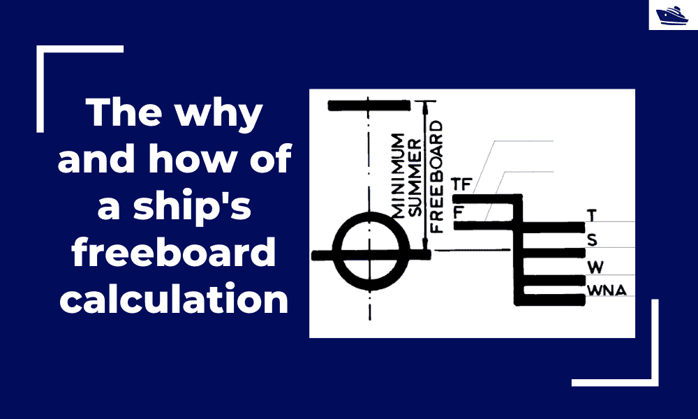
The why and how of freeboard calculation of a ship
Introduction Freeboard is a common term used in vessel operations. Freeboard is the smallest vertical distance between the waterline and the freeboard deck (generally the upper deck) along the length of the vessel. The term ‘smallest’ is of significance, as the height...
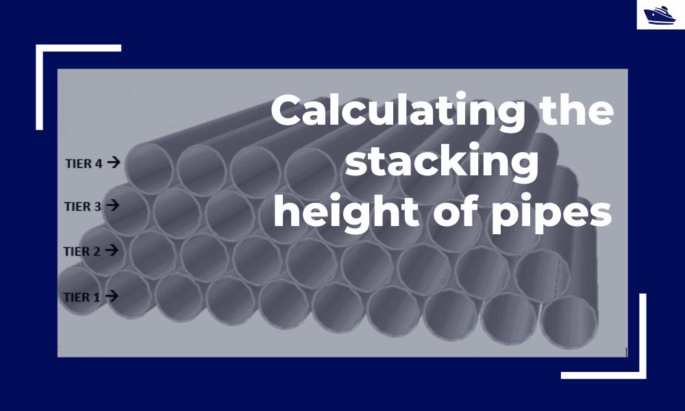
Calculating the maximum stacking height of pipes
Introduction Pipes (or linepipes or joints) are used for multiple purposes and locations in the maritime/offshore industry. Onshore and offshore pipelines are used for transportation of fluids on land, over and underwater. Pipes are fabricated in an onshore facility...
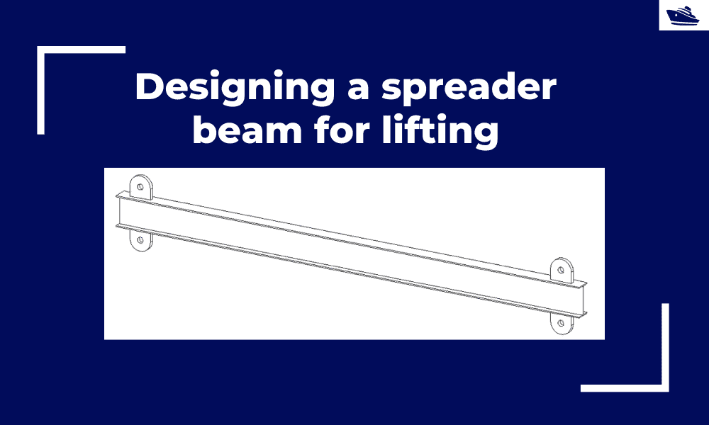
Designing a spreader beam for lifting
Spreader beams are universally applied gear which is widely used in various types of lifting operations, onshore and offshore. In this article, we will explore the design of a basic spreader beam and see what design checks are needed to establish the suitability of a...
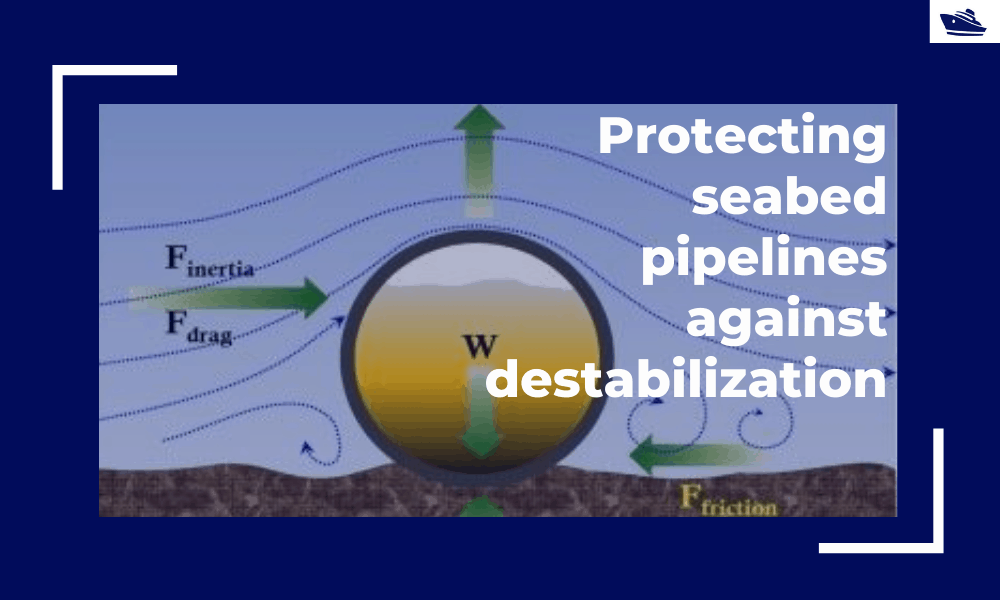
Protecting the seabed pipelines against destabilization: Identifying and qualifying the risk
The Philosophy Cable hydrodynamic stability is one of the most fundamental design topics which are addressed by cable installation engineers. In its simplest form, a simple force balance approach may be considered to ensure that the cable is not displacing...
Safe Towing: Calculating a towline’s catenary and sag
Introduction Towlines connect a tug to the vessel being towed and are defined by multiple characteristics like Weight, Diameter, and Stiffness. The tension in the towline during the towing operation is not static but keeps varying with the distance between the tug and...
Please check out TheNavalArch’s product for planing vessel resistance estimation:

Hi Prem,
I will read this with much of interest.
Brgds
Costas