Resistance estimation for a vessel is a fundamental exercise in design of the vessel. Resistance is a property that depends on the vessel’s shape and form. A conventional ship-shaped vessel with a bulb will have completely different resistance characteristics compared to a high-speed planing vessel.
Resistance estimates are done using various methods – by hydrodynamic modeling/CFD analyses or by model testing for accurate estimates, or by using empirical relations in the preliminary design phase for a fair estimate of the resistance.
Empirical relations too vary depending on the vessel type. While Holtrop-Mennen method is the most popular one that is used for conventional ship forms (usually merchant vessels), it does not apply to high-speed hulls and planing boats.
Planing vessel resistance calculator – TheNavalArch
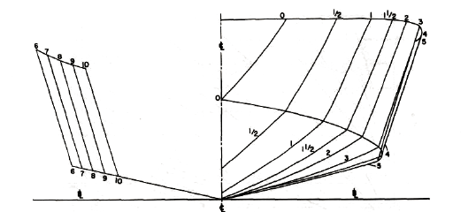
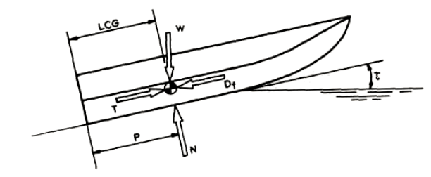
A planing vessel is distinguished form a conventional displacement vessel by the mechanism of weight support. While for a displacement vessel, the buoyancy of the vessel supports its weight, a planing vessel supports its weight by the hydrodynamic lift forces generated when the vessel moves at high speed over water. When the planing vessel is at rest or at low speeds, its weight is supported by its buoyancy, but as it moves with higher speeds, hydrodynamic lift forces are generated by the specially designed hull shape of the planing craft and these lift forces fully support the hull. In some crafts the lift and buoyancy both support the weight. A typical body plan of a planing craft is shown below:
In this article, we will look into a theoretical approach to estimating a planing craft’s performance. A number of resistance tests have been performed by Savitsky (1964) to determine formula for lift and drag of planing vessels, and empirical relations have been provided for the drag.
In this method, at equilibrium, part of the lift is generated by Buoyancy while the rest is generated as hydrodynamic lift. The important parameters of the vessel like its dimensions, speed, displacement etc are taken as inputs, and parameters like trim angle, wetted length of the keel etc. are determined. These parameters are then used to determine the resistance of the vessel.
The method and steps can be broken down into the following:
- Step 1 – Calculate the Displacement Froude number: The first parameter to be calculated is the displacement Froude number. It is defined thus
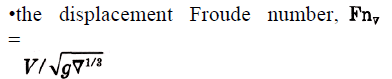
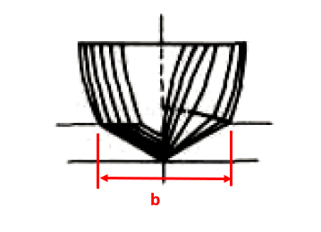
- Step 2 – Calculate the Froude number based on ‘b’: Here, ‘b’ is the maximum beam of the vessel over chine or spray strips. This is the beam of the planing area of the vessel
CV = V/√(gb)
Planing vessel resistance calculator – TheNavalArch
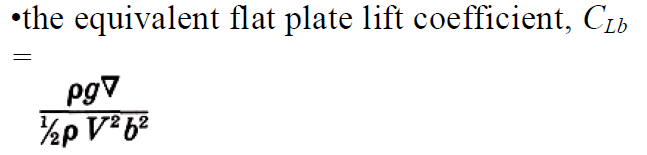
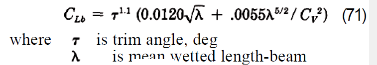
- Step 3 – Calculate the equivalent flat plate lift coefficient: This is calculated by using the formula:
- Step 4 – Calculate the lift coefficient for a finite deadrise: Depending on the deadrise angle β, the lift coefficient for a finite deadrise is calculated from the flat plate lift coefficient by using the following formula:
![]()
- Step 5 – Calculate the p/b ratio, where p = longitudinal center of gravity (LCG) of the vessel (see below)
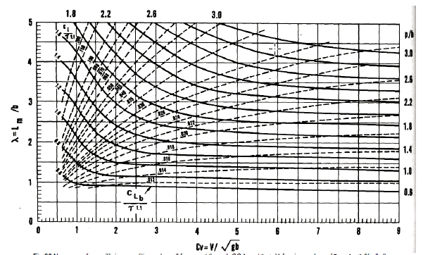
- Step 6 – Calculate the mean wetted length-beam ratio: This is the ratio λ = Lm/b, which is obtained from the Koelbel’s curves.
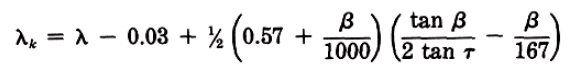
- Step 7 – Calculate the trim of the vessel in equilibrium: This is calculated by using the Savitsky formula:
Here λ is the ratio of the mean wetted length to the beam of the planing area, i.e., Lm/b, obtained in Step 6
- Step 7 – Calculate the keel-wetted length ratio: This is calculated by using the formula:
- Step 8 – Check if the vessel is fully planing: If λk <= LWL/b, then it is fully planing, i.e., the bow is clear of water, else it is not. If it is fully, planing, then the method is valid, else this method is not applicable for vessels not fully planing
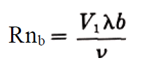
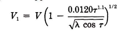
- Step 9 – Use the formula to calculate resistance:

W is displacement. Here, CFO is calculated from ITTC Line, using the following formula
CFO = 0.075/(log10Rn -2)2
Do check our our product Planing Vessel Resistance Calculator
References
- https://en.wikipedia.org/wiki/Planing_(boat)
- Principles of Naval Architecture Second Revision, Volume II Resistance, Propulsion and Vibration
Disclaimer: This post is not meant to be authoritative writing on the topic presented. thenavalarch bears no responsibility for the accuracy of this article, or for any incidents/losses arising due to the use of the information in this article in any operation. It is recommended to seek professional advice before executing any activity which draws on information mentioned in this post. All the figures, drawings, and pictures are property of thenavalarch except where indicated, and may not be copied or distributed without permission.
Designing the lashings of deck cargo using IMO CSS
Introduction More than 70% of the earth is covered by water, which makes shipping historically the easiest and cheapest way of connecting manufactures and customers across the globe and can be reasonably considered to be the artery of the global economy....
Using MS Excel to evaluate the Stability of existing Barges
Barges are the simplest, and yet most widely used of marine vehicles. They are used for a variety of purposes ranging from carrying cargo in bulk or liquid, to even carrying passengers for short inland cruises. Barges are mostly towed by another barge called a tug,...
The importance of ULS (Ultimate Longitudinal Strength) and how to assess it for a damaged hull
by Alessandro La Ferlita, Naval Architect Ultimate hull girder strength represents the maximum capacity, of the hull girder beyond the structure fails. In fact, if the vertical bending moment applied overcomes a certain maximum value, the ship can collapse (Figure 1)...
How to calculate the strength of Midship Section of a Ship
The mid-ship section of a ship is a defining structural drawing of the vessel. It represents the most critical structural parameter of the vessel – its global strength. To assess how much of the bending moment (hog and sag) the vessel can tolerate, it is important to...
How to use empirical formulas to estimate the resistance of a Ship
How to use empirical formulas to estimate the resistance of a Ship Resistance estimation holds immense importance in the design stage of a vessel. Based on the results of the resistance estimation of a vessel, the selection of the right propulsion system is done....
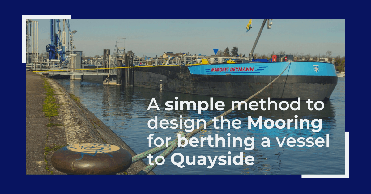
Designing the berth mooring of your vessel with this simple yet effective method
A vessel at berth experiences much lower forces compared to a vessel in the open sea due to the milder environment, but it still requires a mooring configuration suited to the forces it experiences, and also suitable for the type of berthing configuration adopted. The...

Bulbous Bows – History and Design
by Bijit Sarkar, Naval Architect Introduction The eternal search of a naval architect – a perfect bow. Sadly, it never exists. Different bow forms are good for different types, sizes of vessels and seaways. What does a naval architect want out of the bow he designs?...
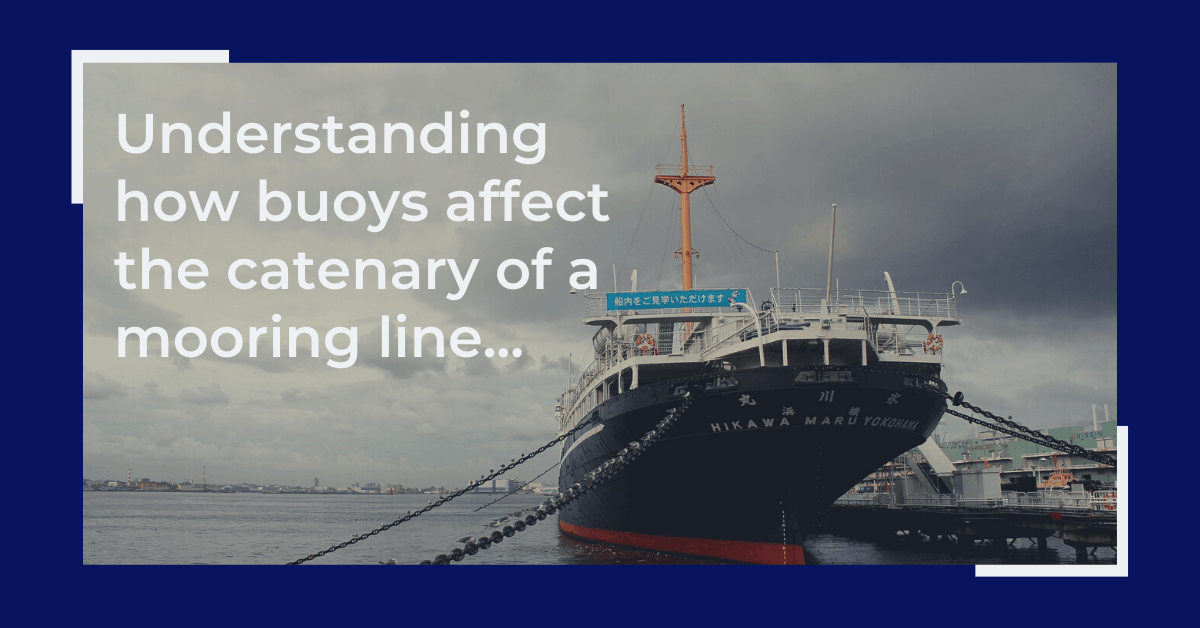
Understanding how buoys affect the catenary of a mooring line
What is a mooring line? Mooring lines generally comprise ropes, wires, chains or combination of wire and chain used to keep ships, offshore platforms and other floating vessels in position. It connects the structure either to the seabed using an anchor or the quay...
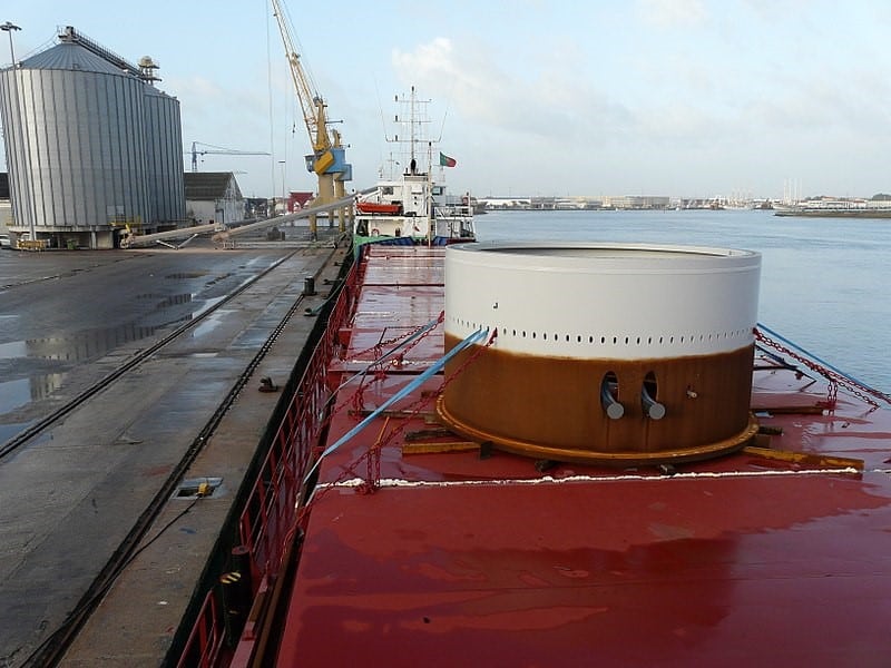
Calculating forces on a ship’s deck cargo – a simplified approach
A cylindrical deck cargo (Source: Wikimedia) Introduction A ship’s deck is used to transport many different types of cargo – from containers to large structures like cranes or heavy modules of an offshore production plant. During transport, the ship suffers from...
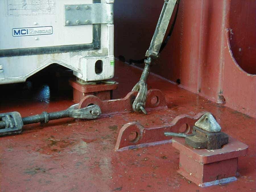
Designing a pad-eye: little items with big intricacies
Pad-eyes are one of the smallest and most universally used structural items in the maritime and Oil & Gas industry. They are used for a variety of purposes too: from a simple seafastening of a cargo to deck of a vessel, to complicated lifting operations involving...
Please check out TheNavalArch’s product for planing vessel resistance estimation:

Hi Prem,
I will read this with much of interest.
Brgds
Costas