by Bijit Sarkar, Naval Architect
Introduction
The eternal search of a naval architect – a perfect bow. Sadly, it never exists. Different bow forms are good for different types, sizes of vessels and seaways.
What does a naval architect want out of the bow he designs?
The history of the bulbous bow
I do think that after Archimedes’ Principle, the concept of bulbous bow is the first really great thing that happened in naval architecture. All the while naval architects were tuning their designs here and there – angle of entrance, a finer shape, avoiding that shoulder and hoping for a 2% shaving off the resistance when the concept of bulbous bow gave it a quantum leap, saving a whopping 5-8%, albeit for a specific Froude number range.
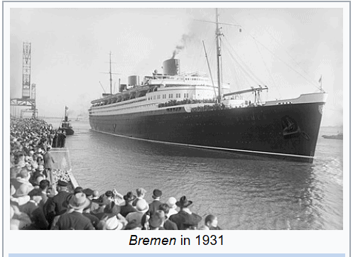
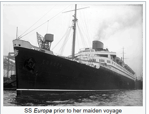
The first ship designed with a bulbous bow was a German ocean – liner called SS Bremen , owned by Norddeutscher Lloyd Line . She, and her sister ship SS Europa (Later SS Liberte’) had high speed steam turbine engines and a stream lined profiles and started plied the transatlantic sea route in the late 1920s. These two ships were national symbols of pride for Germany for pre-war years of 1930s. She held the prestigious Blue Riband, an unofficial accolade given to the passenger liners in the Transatlantic route of that era with the record highest (average) speed.
Source : Wikipedia
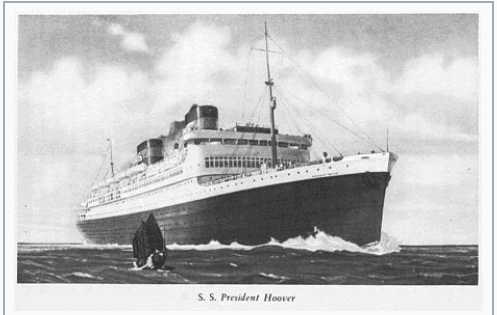
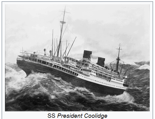
The Americans followed soon with SS President hoover and SS President Coolidge in 1931, although their bulbs were considered to be experimental, by both owners and shipyards
Source : Wikipedia
|
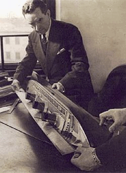
Vladimir Yukevich working on the design of SS Normandie |
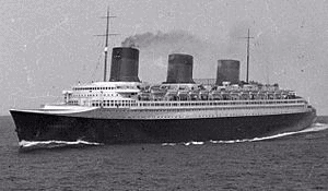
SS Normandie , designed by Vladimir Yukevich, had a superbly designed hull with a massive bulb at the bow, resulting in a clean entry into the water flow and a highly reduced bow wave. This reduced the wave resistance considerably, allowing it to attain a trial speed of 32.2 knots
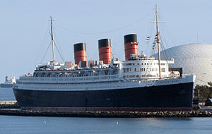
Normandie’s arch rival in the ocean passage trade, RMS Queen Mary, was of similar dimension and achieved speed of 32.84 knots at trial.
However, here are the comparison of their main Propulsions, showing that Queen Mary needed 30% more power .
|
 |
 |
||||
|
|
||||
|
|
||||
| British ocean liner built by John Brown & Company in Clydebank, Scotland | French ocean liner built in Saint-Nazaire, France |
Source : Wikipedia
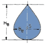
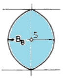
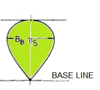
Different bulb shapes in use
| DIFFERENT BULB SHAPES | ||
|
Delta |
Oval |
Nabla |
|
Taylor Bulb Pear Shaped Bulb |
Elliptical Circular Cylindrical Lens Shaped |
Most common form today |
|
“U” shaped hulls Large variations of draught Wave piercing bow |
“U” or “V” shaped hulls |
“V” shaped hulls Clearly defined loaded and ballasted draughts |
| More susceptible to slamming | Less susceptible to slamming | Less susceptible to slamming |
The X-bow: a modern innovation
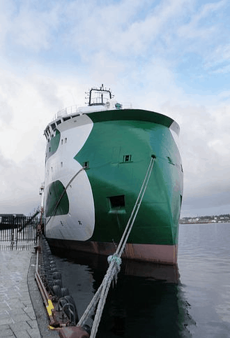 Source : Ulstein website Source : Ulstein website |
The first ship with X-bow design is MV Bourbon Orca, anchor handling tug supply vessel (AHTS) built for Bourbon Offshore Norway, the Norwegian division of the French Groupe Bourbon.by Ulstein (2006). She was awarded Ship of the Year 2006, both by Skipsrevyen[4] and Offshore Support Journal. In 2007, the Bourbon Orca design model was included in the London Science Museum’s display of innovative technology. The vessel’s operator claims that the design achieves higher speed and a calmer motion in head, rough seas. |
As an extension of the bulb from, Ulstein came out with the concept of X-bow in the year 2005 and the first ship was commissioned in 2006 .
The bow, by incorporating a large forebody coming right out of water and sloping aft right to level of a high first exposed deck, causes a different volume distribution with a tapered fore ship shape as well as sectional angles, resulting in a wave piercing effect at small wave heights, and also reduces pitching and bow impact loads in rougher seas with bigger waves.
Major benefits of the X-BOW , as per Ulstein, are as follows
- Improved power efficiency
- Soft entry in waves
- Very low levels of noise and vibrations
- Reduced bow impact and slamming
- Reduced wave-induced vibrations
- Improved resting time
- Lower acceleration levels
- Lower pitch response due to volume
- More comfortable on board conditions
- Lower speed loss
- Reduced spray
However, X-bow is more suitable for bigger vessels in rough seas. Because of the shape, the spray runs up the hull and hence to avoid the spray hitting your bridge window, the same has to be high. A small vessel may not have those many decks and will naturally have problems. The windage area increases and also the risk of plunging deep into the sea. For a conventional bow, as she plunges deep into the sea, the displaced volume increases, increasing the momentum to reduce pitching motion and acceleration. In case of a ship with X-bow, it is the opposite.
Parameters affecting the design of a bulbous bow
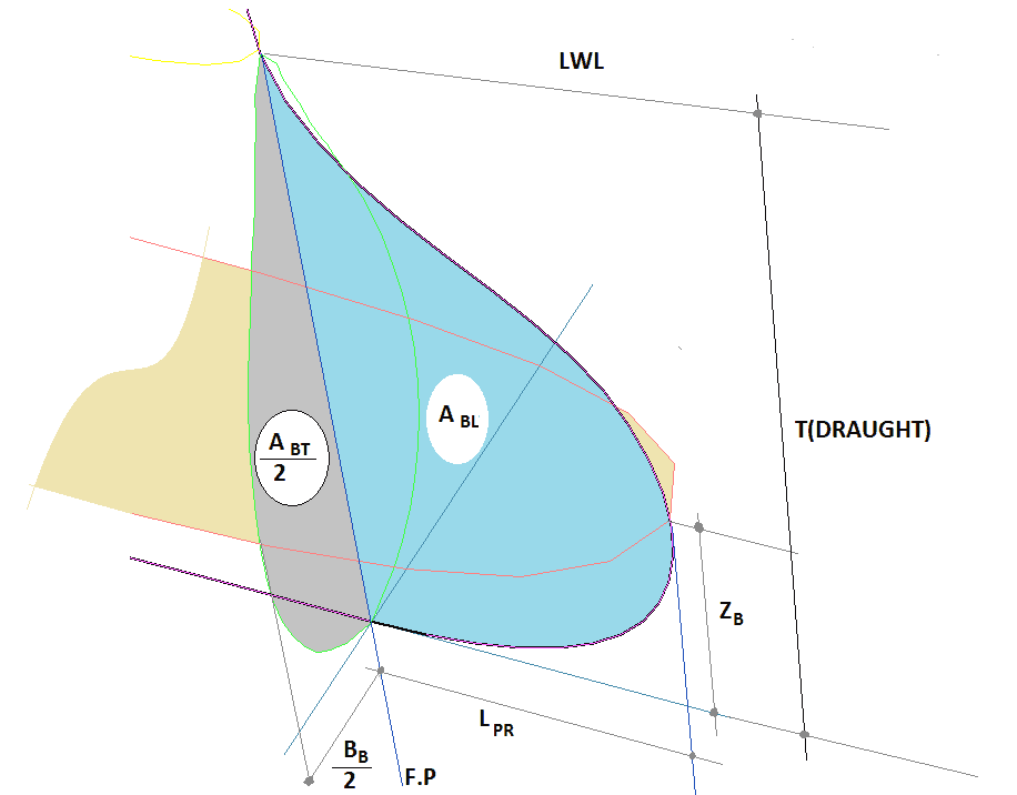
A bulbous bow is defined by the following parameters, which are also shown in the diagram below.
| BB | = | MAX WIDTH OF BULB |
| LPR | = | LENGTH OF BULB MEASURED FROM FP |
| ZB | = | HT. OF TIP OF BULB FROM BASELINE |
| ABT | = | TRANS. SECTION AREA AT F.P |
| ABL | = | LONG. SECTION AREA OF BULB AT CENTRELINE |
| VPR | = | VOLUME OF BULB FROM F.P TO TIP |
Below are the linear and non-linear form co-efficients from which the bulb parameters are derived
| LINEAR | NON-LINEAR | ||||
| NAME | DESC. | FORMULA | NAME | DESC. | FORMULA |
| CBB | BREADTH CO-EFFN | BB/B | CABT | CROSS SECTION CO-EFFN | ABT/AMS |
| CLPR | LENGTH CO-EFFN | LPR/LPP | CABL | LONG SECTION CO-EFFN | ABL/AMS |
| CZB | HEIGHT CO-EFFN | ZB/TFP | C∇PR | VOLUMETRIC CO-EFFN | VPR/∇ |
|
B = BREADTH OF SHIP BB = BULB BREADTH AT FP LPP = LENGTH BTWEEN PERPENDICULARS LPR = PORTRUDING LENGTH OF BULB TFP = DRAFT AT FORWARD PERPENDICULAR |
ABT = CROSS SECTIONAL AREA AT F.P AMS = MIDSHIP AREA ABL = LONG. CROSS SECTIONAL AREA FORD OF F.P VPR = VOLUME OF BULB FORD OF F.P |
||||
| TYPICAL RANGE OF CO-EFFICIENTS ( KRACHT , 1970) | |||||
| LINEAR | NON-LINEAR | ||||
| NAME | MIN. | MAX. | NAME | MIN. | MAX. |
| CBB | 0.170 | 0.200 | CABT | 0.064 | 0.122 |
| CLPR | 0.018 | 0.031 | CABL | 0.068 | 0.146 |
| CZB | 0.260 | 0.550 | C∇PR | 0.0011 | 0.00272 |
How does the bulb work?
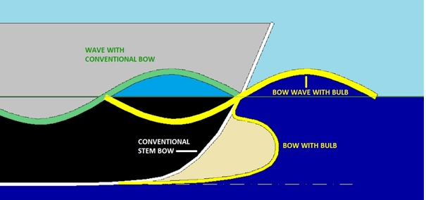
As one can see in the diagram, a conventional bow creates a bow wave. That means a high pressure zone – much like as if the ship is pushing against a pileup of water. The energy going into this shows up as bigger waves and goes to contribute to wave resistance.
In contrast, the bulb due to its forward motion is pushing the water sideways and up , creating a crest ahead of the ship , with the trough occurring aft of hull entry, which necessarily means reducing the pressure on the hull, resulting in lower wave resistance. The higher the speed within that Froude number range , the more is the effect of the bulb
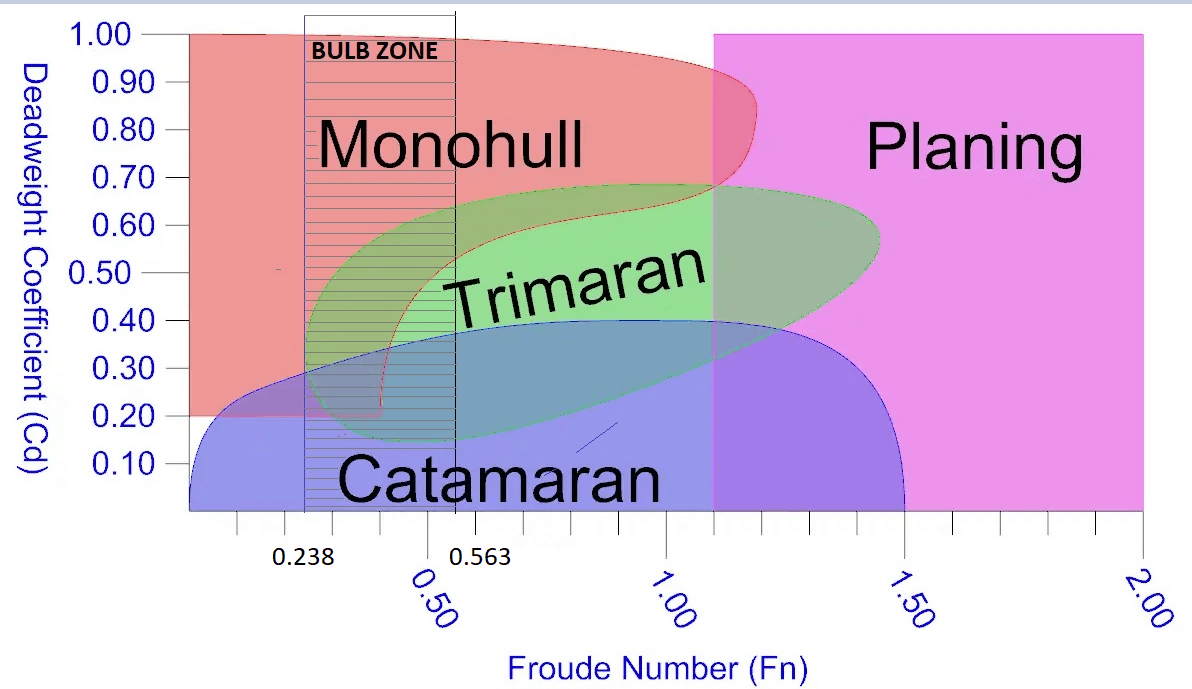
Apart from reducing the resistance at the specific Froude number range (>0.238 and < 0.563) , the effect on sea-keeping characteristics are also important. Bulbs typically are v-shaped on the bottom to minimize slamming in rough seas. The large volume so far ahead of the ship produces extra buoyancy and a high moment that counteracts pitching motion.
The following diagram is a quick selection help for selection of the type of hull and within that the zone of applicability for the bulb. The diagram is qualitative and designers should use their own discretion.
CFD analysis of ships with bulbous bow
Now that Naval architects have huge computing power at their disposal and with the advancement of technology in the area of computational numerical methods, the quality of ship design has advanced and refined.
While I still rank a model test to be a far more reliable tool to estimate the resistance of the ship, Iterative CFD analysis with continuous changes in the hull form can result in a far better hull form to begin the model test. To change the model a number of times physically is a time consuming and costly affair and CFD can make the process faster, better and more economic. Bearing in mind that most of this work has to be done at a pre-bid state, where a return is not always assured, CFD is definitely a useful tool .
References:
- Design Optimization of the Lines of the Bulbous Bow of a Hull Based on Parametric Modeling and Computational Fluid Dynamics Calculation
- Weilin Luo i,ii and Linqiang Lan ii
- School of Mechanical Engineering and Automation, Fuzhou University, Fuzhou 350116, China;
- Fujian Province Key Laboratory of Structural Performances in Ship and Ocean Engineering,
- Fuzhou 350116, China
- Design & Construction of Bulbous Bow
- Manuel Ventura
- Website – Ulstein
- Design Principles of Ships and Marine Structures – Prof. S.C.Mishra
- Basic Ship Propulsion – Prof. J.P.Ghose & Prof. R.P.Gokarn
Disclaimer:
The views, information, or opinions expressed are solely those of the author and do not necessarily represent those of TheNavalArch Pte Ltd and its employees
Bijit Sarkar
Naval Architect
Bijit Sarkar is a graduate of 1981 from Indian Institute of Technology, Kharagpur with honors in Naval Architecture followed by Ocean Management Training from International Ocean Institute, Malta. He has been a designer, an innovative one, all his life – designing ships of all varieties but primarily military vessels. Apart from marine, he has design experience in a wide gamut of engineering. Attached to his alma-mater as member, advisory in the expansion programs of the departments, his special areas of interest , where he is putting a lot of effort into are Renewable Energy, Pollution and global effects, Artificial Intelligence in shipbuilding and Bio-mimicry.
The why and how of freeboard calculation of a ship
Introduction Freeboard is a common term used in vessel operations. Freeboard is the smallest vertical distance between the waterline and the freeboard deck (generally the upper deck) along the length of the vessel. The term ‘smallest’ is of significance, as the height...

Using MS Excel to evaluate the Stability of existing Barges
Barges are the simplest, and yet most widely used of marine vehicles. They are used for a variety of purposes ranging from carrying cargo in bulk or liquid, to even carrying passengers for short inland cruises. Barges are mostly towed by another barge called a tug,...
How to calculate the strength of Midship Section of a Ship
The mid-ship section of a ship is a defining structural drawing of the vessel. It represents the most critical structural parameter of the vessel – its global strength. To assess how much of the bending moment (hog and sag) the vessel can tolerate, it is important to...
How to use empirical formulas to estimate the resistance of a Ship
How to use empirical formulas to estimate the resistance of a Ship Resistance estimation holds immense importance in the design stage of a vessel. Based on the results of the resistance estimation of a vessel, the selection of the right propulsion system is done....
Designing a pad-eye: little items with big intricacies
Pad-eyes are one of the smallest and most universally used structural items in the maritime and Oil & Gas industry. They are used for a variety of purposes too: from a simple seafastening of a cargo to deck of a vessel, to complicated lifting operations involving...
Cathodic Protection – Ships, Offshore Platforms, FPSO’s and Pipelines: a comparison
Cathodic protection of a structure is an exercise which requires close study of the structure on which it is going to be implemented. The type and quantity of cathodic protection by anodes will depend upon multiple factors: the Geometry of the Structure, the...
Role of a naval architect – a walkthrough (Part – 1)
This is the first in a series of articles on 'Role of a Naval Architect' by Mr Bijit Sarkar, a Naval Architect with 35+ years of experience in ship design and shipbuilding. I would define a naval architect as one who has the ability to greet the client as he/she walks...
The bulbous bow – why some ships have it and others don’t
By Tamal Mukherjee, This is the Part 1 of a two part article on the Bulbous Bow. Part 2 can be accessed here *This article originally appeared in May 2019 edition of Marine Engineers Review (India), the Journal of Institute of Marine Engineers India. It is being...
Removing Human Error in Ship Performance Analysis
Introduction Shipping is the most dominant means of transport that facilitate global trade. Over 90% of world trade is done by ships[1]. Fuel onboard ships, commonly referred to as "bunkers", has become the largest cost item of a ship's Operational Expenses (OPEX),...
CFD in the marine industry: today and tomorrow
In the world of advancing digital technology, it important to identify all the best ways to apply it to the extremely complex task of designing a ship. Riding the wave of the rapid progress of High Performance Computing, Computational Fluid Dynamics (CFD)...



To Bijit Sarkar I congratulate you on your meritorious presentation on bulbous bows. You have been able to present all aspects of bulbous science one table – theory, design, application, and history supported by strong visuals. Only one development appears to have been not mentioned – ram bow ( rather long cylindrical extension from bow-line) applicable to mammoth tankers, bulkers, etc. I wish you to carry on like this. Prof M K Ghosh Roy
As a non-specialist with an engineering background, I enjoyed reading this summary of the benefits of bulbous bows and the various considerations that go into their design. It is fascinating that a feature of such small relative size delivers significant physical and economic benefits. In that regard it is similar to the winglets that can be seen on the wingtips of modern commercial airliners, although the physical mechanism (reduction of vortex drag or induced drag) is different.
I would appreciate reading about any further advances along these lines, perhaps from an R&D perspective. Here are two such thoughts: (i) economic and mechanical viability of adjustable bulbs that could theoretically be optimized for different loading and speed conditions; (ii) any ideas for similar wave- (or wake-) modifying features at the stern.
I look forward to more articles from the author.
I want to refer to my use of Stelio’s recent post in a comment to Facebook. Thanks!