Introduction
Chocks are used universally for mooring and towing operations on ships.
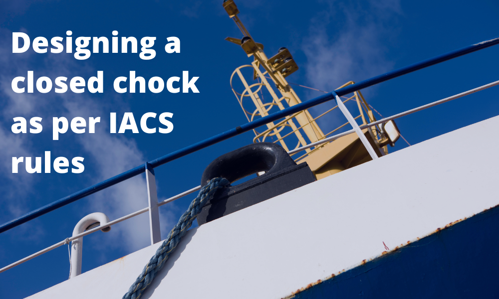
For towing operations, Chocks are used for guiding the towing rope from the winch through the outer shell of the vessel to the tug. For mooring operations, the chock is used to guide the mooring rope from bollard/bitt on the deck of the vessel through the outer shell of the vessel to the mooring points on the jetty/pier/quay. A typical closed chock design looks like the below:
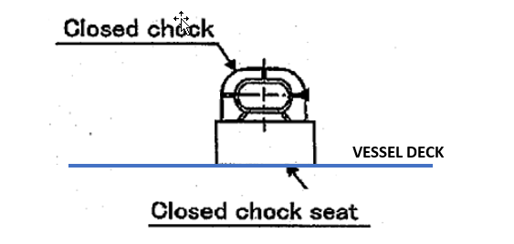
The closed chock has a body which is round in shape and it has a rectangular shaped seating that is welded to the deck of the vessel.
This article talks about designing a closed chock as per the relevant requirement of the International Association of Classification Societies (IACS) rules. The guiding rule followed is the Unified Requirement (UR) A2 Rev 5 (Sep 2020).
In this article we’ll see what kind of forces are expected on a chock, and what design stresses we need to evaluate it for, to check its suitability for an operation.
Design Load
The design load on a chock will depend on the purpose the chock is deployed for.
When the chock is used for towing, there are two scenarios of towing that UR A2 covers:
- Normal towing operations: this relates to towing in ports and sheltered waters
- Other towing operations: to assist the ship in case of emergency as given in SOLAS Regulation II-1/3-4 Paragraph 2.
During normal towing operations, the force on the chock comes from the load on the towline that connects the vessel to the tug pulling it. The maximum bollard pull of the tug will be the governing load on the chock. During emergency (other) towing operations, the governing force becomes the Ship’s Design Maximum Breaking Load as defined in UR A2 thus:
Ship Design Minimum Breaking Load (MBLSD) means the minimum breaking load of
new, dry mooring lines or tow line for which shipboard fittings and supporting hull
structures are designed in order to meet mooring restraint requirements or the towing
requirements of other towing service.
If the chock is used for mooring, then the loads on the mooring lines will be the governing loads. In this case, the Ship’s Design Maximum Breaking Load (SDMBL) is taken as the design load for mooring loads on the ship’s fittings.
Load Cases
The chock can be subject to different load cases, depending on the angle at which the design load is acting on the chock.
The design load (DL) is the load acting on the towing/mooring line.
The next question is: at what angle these forces should be considered on the chock?
Case 1: Angle in the horizontal plane
The chock’s purpose is to guide the line from winch/bollard to the pier/tug. This will result in the line making an angle around the chock’s inner surface as shown below. The angle(θ) depends upon the position of the winch/bollard and the position of the pier/tug. This angle may vary depending on the use case, and so a conservative minimum angle should be used for design.
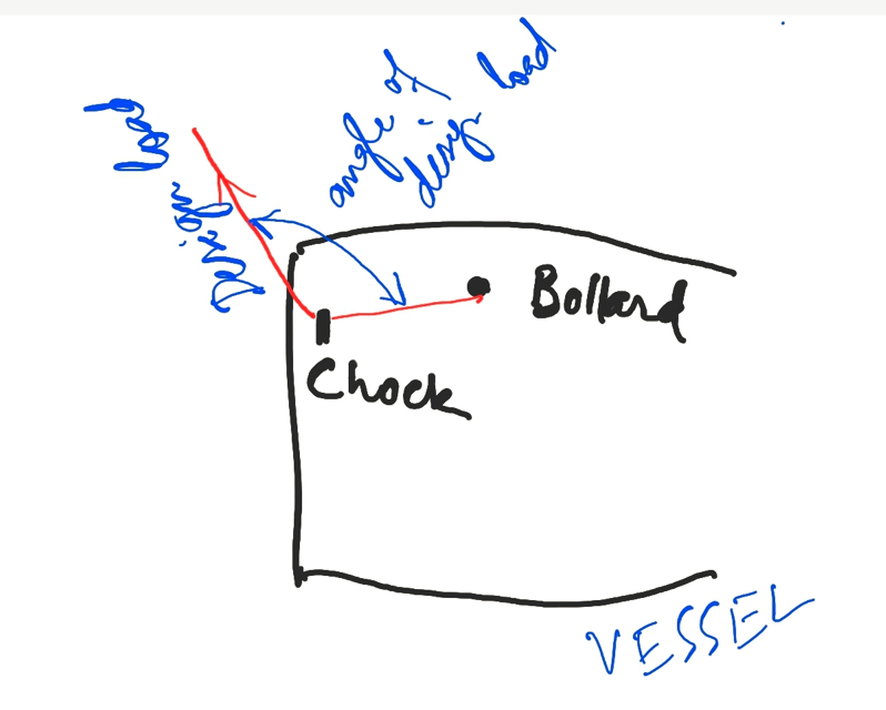
In case the determination of this angle is not feasible, it is taken as zero. Depending on the angle input, the effective (resultant) load on the chock can be calculated as follows:
F (resultant load on chock) = 2 x DL x cos(θ), see figure below

Design load and angle on the chock (source: IACS UR A2, A.2.1.3)
We can see that if we take θ as zero, the resultant force on the chock F becomes 2 x DL, and this represents a worst-case scenario. If a reliable assessment of θ is not available, we should take F = 2 x DL.
Case 2: Angle in the vertical plane
The previous loading case had the force F in the horizontal plane. There’s another possibility of loading when the line from the bollard/winch on the deck and through the chock goes vertically down, thus resulting in the force in the vertical plane. This scenario is depicted below.
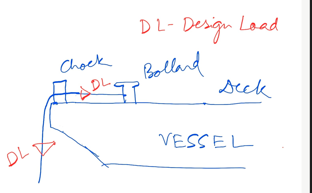
A force diagram on the chock will look like the below:
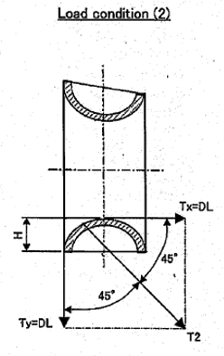
Here, we can see the design load on the line (DL) acts as Tx and Ty in the horizontal and vertical directions on the chock.
Stress Checks
Once the loading conditions are established, the next will be the stress checks for the chock structure.
The stress check will include the following for each load case:
- Bending Stress Check on the Chock
- Shear Stress due to horizontal component of load
- Axial stress due to vertical component of the load
- Normal stress check (bending + axial)
- Shear, tensile, bending and total stress on the weld between chock and chock seating
The same set of stress checks will also have to be performed for the chock seating which connects the chock to the deck of the vessel. The weld between the seating and deck will also need to be checked for all the applicable stresses.
Once stress checks are done and the chock design verified, the chock can be considered fit for the purpose it’s built for.
Disclaimer: This post is not meant to be authoritative writing on the topic presented. thenavalarch bears no responsibility for the accuracy of this article, or for any incidents/losses arising due to the use of the information in this article in any operation. It is recommended to seek professional advice before executing any activity which draws on information mentioned in this post. All the figures, drawings, and pictures are property of thenavalarch except where indicated, and may not be copied or distributed without permission.
Marine Propeller Shafting and Shafting Alignment – Part 1
*****This article first appeared in July 2018 edition of Marine Engineers' Review (MER), India. We're reproducing it for the readers of our blog***** Abstract: Since 2013, Shaft Alignment Practice has undergone a change, with developments of Analysis tools. At the...
Using Class Rules to assess the Longitudinal Strength requirement of Barges
Introduction The longitudinal strength of a vessel is integral to its evaluation for a given purpose. To get an introduction to the topic, please refer to our other article https://thenavalarch.com/longitudinal-strength-ships-introduction/ In this article, we’ll see...
The four important factors for a ship’s windage area calculations
Introduction The windage area of a vessel or offshore structure is the area that is exposed directly to the wind. As is obvious, this is the area of all items above the waterline. This will include Part of the hull/offshore structure above the waterline...
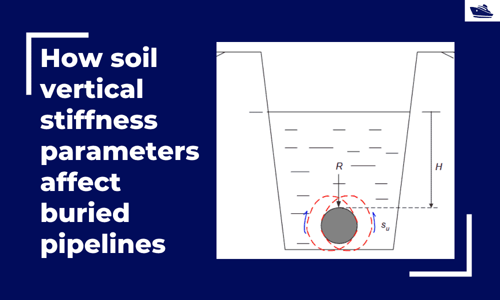
How soil vertical stiffness parameters affect buried pipelines
Introduction Pipe soil interaction is a critical subject of analysis in the field of the offshore industry. A pipe once buried in the seabed is usually in equilibrium with the surrounding soil. There are however various forces which are still in action even if the...
Three simple but useful calculations when towing a Vessel
In this article, we will explore three simple but useful calculations that can be used for towing operations. They are: Towline Stiffness Propeller race Towing bridle force DNV-RP-H1o3, Modelling and Analysis of Marine Operations, FEBRUARY 2014 has been referenced...
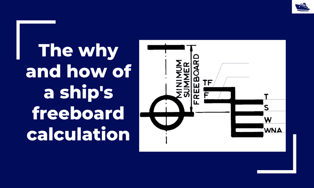
The why and how of freeboard calculation of a ship
Introduction Freeboard is a common term used in vessel operations. Freeboard is the smallest vertical distance between the waterline and the freeboard deck (generally the upper deck) along the length of the vessel. The term ‘smallest’ is of significance, as the height...
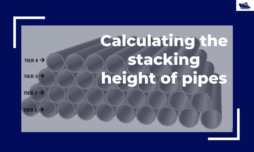
Calculating the maximum stacking height of pipes
Introduction Pipes (or linepipes or joints) are used for multiple purposes and locations in the maritime/offshore industry. Onshore and offshore pipelines are used for transportation of fluids on land, over and underwater. Pipes are fabricated in an onshore facility...
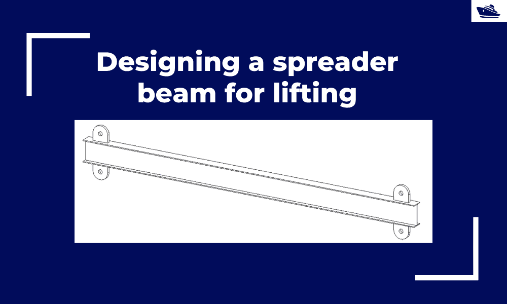
Designing a spreader beam for lifting
Spreader beams are universally applied gear which is widely used in various types of lifting operations, onshore and offshore. In this article, we will explore the design of a basic spreader beam and see what design checks are needed to establish the suitability of a...
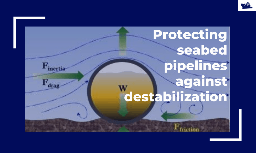
Protecting the seabed pipelines against destabilization: Identifying and qualifying the risk
The Philosophy Cable hydrodynamic stability is one of the most fundamental design topics which are addressed by cable installation engineers. In its simplest form, a simple force balance approach may be considered to ensure that the cable is not displacing...
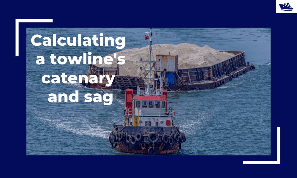
Safe Towing: Calculating a towline’s catenary and sag
Introduction Towlines connect a tug to the vessel being towed and are defined by multiple characteristics like Weight, Diameter, and Stiffness. The tension in the towline during the towing operation is not static but keeps varying with the distance between the tug and...
Please check out TheNavalArch’s product for IACS chock design:

Send me some info.
Need the design calculation for designing chock