Introduction
Chocks are used universally for mooring and towing operations on ships.
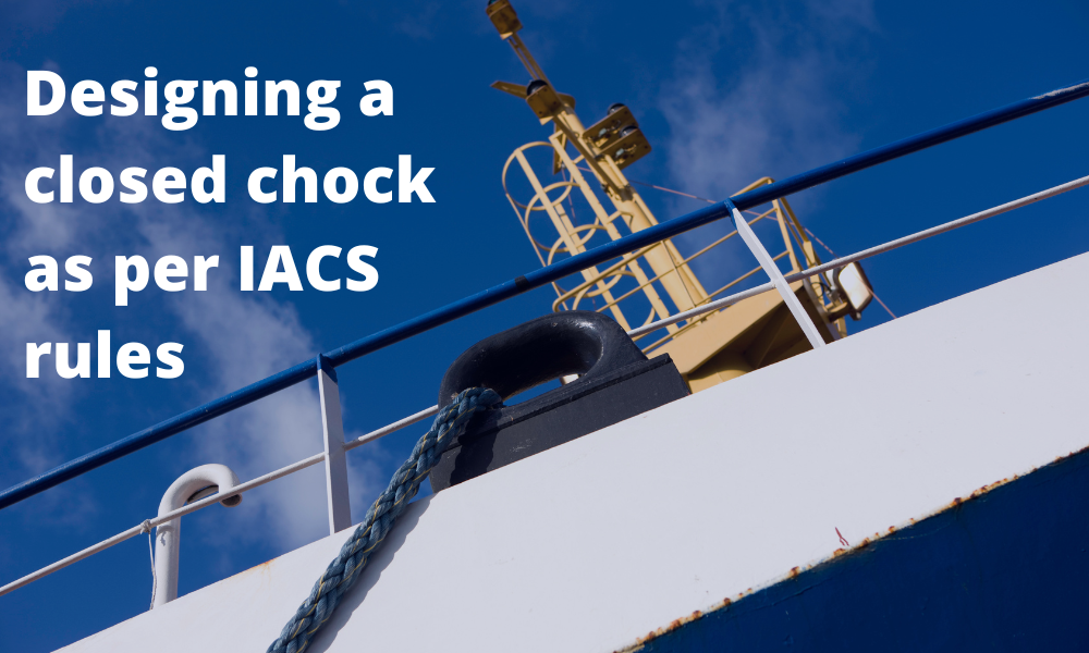
For towing operations, Chocks are used for guiding the towing rope from the winch through the outer shell of the vessel to the tug. For mooring operations, the chock is used to guide the mooring rope from bollard/bitt on the deck of the vessel through the outer shell of the vessel to the mooring points on the jetty/pier/quay. A typical closed chock design looks like the below:
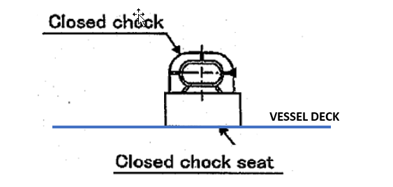
The closed chock has a body which is round in shape and it has a rectangular shaped seating that is welded to the deck of the vessel.
This article talks about designing a closed chock as per the relevant requirement of the International Association of Classification Societies (IACS) rules. The guiding rule followed is the Unified Requirement (UR) A2 Rev 5 (Sep 2020).
In this article we’ll see what kind of forces are expected on a chock, and what design stresses we need to evaluate it for, to check its suitability for an operation.
Design Load
The design load on a chock will depend on the purpose the chock is deployed for.
When the chock is used for towing, there are two scenarios of towing that UR A2 covers:
- Normal towing operations: this relates to towing in ports and sheltered waters
- Other towing operations: to assist the ship in case of emergency as given in SOLAS Regulation II-1/3-4 Paragraph 2.
During normal towing operations, the force on the chock comes from the load on the towline that connects the vessel to the tug pulling it. The maximum bollard pull of the tug will be the governing load on the chock. During emergency (other) towing operations, the governing force becomes the Ship’s Design Maximum Breaking Load as defined in UR A2 thus:
Ship Design Minimum Breaking Load (MBLSD) means the minimum breaking load of
new, dry mooring lines or tow line for which shipboard fittings and supporting hull
structures are designed in order to meet mooring restraint requirements or the towing
requirements of other towing service.
If the chock is used for mooring, then the loads on the mooring lines will be the governing loads. In this case, the Ship’s Design Maximum Breaking Load (SDMBL) is taken as the design load for mooring loads on the ship’s fittings.
Load Cases
The chock can be subject to different load cases, depending on the angle at which the design load is acting on the chock.
The design load (DL) is the load acting on the towing/mooring line.
The next question is: at what angle these forces should be considered on the chock?
Case 1: Angle in the horizontal plane
The chock’s purpose is to guide the line from winch/bollard to the pier/tug. This will result in the line making an angle around the chock’s inner surface as shown below. The angle(θ) depends upon the position of the winch/bollard and the position of the pier/tug. This angle may vary depending on the use case, and so a conservative minimum angle should be used for design.
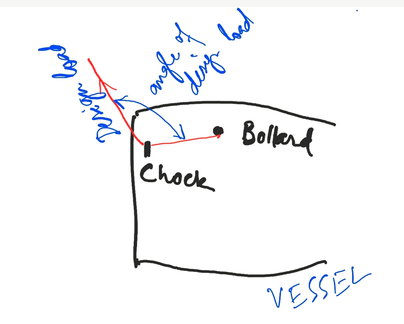
In case the determination of this angle is not feasible, it is taken as zero. Depending on the angle input, the effective (resultant) load on the chock can be calculated as follows:
F (resultant load on chock) = 2 x DL x cos(θ), see figure below

Design load and angle on the chock (source: IACS UR A2, A.2.1.3)
We can see that if we take θ as zero, the resultant force on the chock F becomes 2 x DL, and this represents a worst-case scenario. If a reliable assessment of θ is not available, we should take F = 2 x DL.
Case 2: Angle in the vertical plane
The previous loading case had the force F in the horizontal plane. There’s another possibility of loading when the line from the bollard/winch on the deck and through the chock goes vertically down, thus resulting in the force in the vertical plane. This scenario is depicted below.
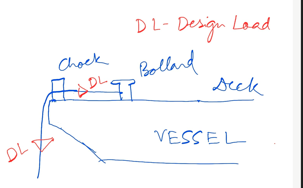
A force diagram on the chock will look like the below:
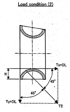
Here, we can see the design load on the line (DL) acts as Tx and Ty in the horizontal and vertical directions on the chock.
Stress Checks
Once the loading conditions are established, the next will be the stress checks for the chock structure.
The stress check will include the following for each load case:
- Bending Stress Check on the Chock
- Shear Stress due to horizontal component of load
- Axial stress due to vertical component of the load
- Normal stress check (bending + axial)
- Shear, tensile, bending and total stress on the weld between chock and chock seating
The same set of stress checks will also have to be performed for the chock seating which connects the chock to the deck of the vessel. The weld between the seating and deck will also need to be checked for all the applicable stresses.
Once stress checks are done and the chock design verified, the chock can be considered fit for the purpose it’s built for.
Disclaimer: This post is not meant to be authoritative writing on the topic presented. thenavalarch bears no responsibility for the accuracy of this article, or for any incidents/losses arising due to the use of the information in this article in any operation. It is recommended to seek professional advice before executing any activity which draws on information mentioned in this post. All the figures, drawings, and pictures are property of thenavalarch except where indicated, and may not be copied or distributed without permission.
Designing the lashings of deck cargo using IMO CSS
Introduction More than 70% of the earth is covered by water, which makes shipping historically the easiest and cheapest way of connecting manufactures and customers across the globe and can be reasonably considered to be the artery of the global economy....
Using MS Excel to evaluate the Stability of existing Barges
Barges are the simplest, and yet most widely used of marine vehicles. They are used for a variety of purposes ranging from carrying cargo in bulk or liquid, to even carrying passengers for short inland cruises. Barges are mostly towed by another barge called a tug,...
The importance of ULS (Ultimate Longitudinal Strength) and how to assess it for a damaged hull
by Alessandro La Ferlita, Naval Architect Ultimate hull girder strength represents the maximum capacity, of the hull girder beyond the structure fails. In fact, if the vertical bending moment applied overcomes a certain maximum value, the ship can collapse (Figure 1)...
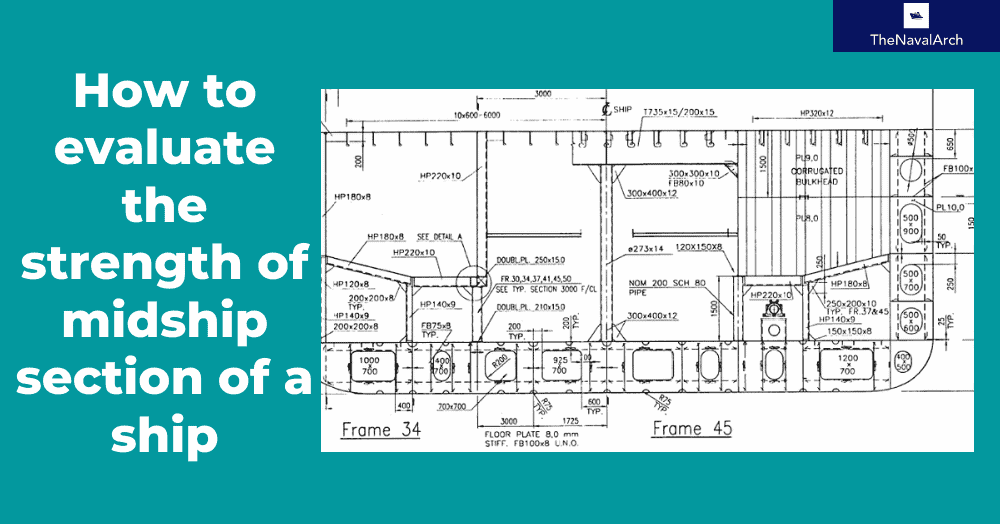
How to calculate the strength of Midship Section of a Ship
The mid-ship section of a ship is a defining structural drawing of the vessel. It represents the most critical structural parameter of the vessel – its global strength. To assess how much of the bending moment (hog and sag) the vessel can tolerate, it is important to...
How to use empirical formulas to estimate the resistance of a Ship
How to use empirical formulas to estimate the resistance of a Ship Resistance estimation holds immense importance in the design stage of a vessel. Based on the results of the resistance estimation of a vessel, the selection of the right propulsion system is done....
Designing the berth mooring of your vessel with this simple yet effective method
A vessel at berth experiences much lower forces compared to a vessel in the open sea due to the milder environment, but it still requires a mooring configuration suited to the forces it experiences, and also suitable for the type of berthing configuration adopted. The...
Bulbous Bows – History and Design
by Bijit Sarkar, Naval Architect Introduction The eternal search of a naval architect – a perfect bow. Sadly, it never exists. Different bow forms are good for different types, sizes of vessels and seaways. What does a naval architect want out of the bow he designs?...
Understanding how buoys affect the catenary of a mooring line
What is a mooring line? Mooring lines generally comprise ropes, wires, chains or combination of wire and chain used to keep ships, offshore platforms and other floating vessels in position. It connects the structure either to the seabed using an anchor or the quay...
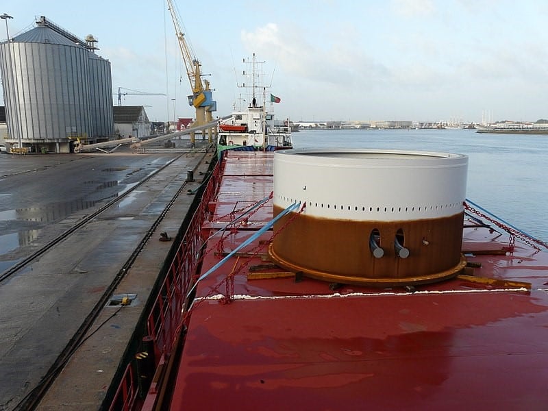
Calculating forces on a ship’s deck cargo – a simplified approach
A cylindrical deck cargo (Source: Wikimedia) Introduction A ship’s deck is used to transport many different types of cargo – from containers to large structures like cranes or heavy modules of an offshore production plant. During transport, the ship suffers from...
Designing a pad-eye: little items with big intricacies
Pad-eyes are one of the smallest and most universally used structural items in the maritime and Oil & Gas industry. They are used for a variety of purposes too: from a simple seafastening of a cargo to deck of a vessel, to complicated lifting operations involving...
Please check out TheNavalArch’s product for IACS chock design:

Send me some info.
Need the design calculation for designing chock