Introduction
Marine transport is the backbone of the global trade and reasonably can be considered to be the artery of the global manufacturing supply chain, as more than four fifths of the world merchandise trade by volume is carried by sea. Undoubtfully, the working horse of merchant shipping industry is the Bulk carrier’s fleet, which with its 842 438 thousand dead-weight is forming 42,6 % of the world’s tonnage has transported 5230 million tons various bulk commodities during 2018 as per UNCTAD Review of Maritime Transport .
An essential part of each merchant sea-trade is the correct determination of the cargo loaded/discharged from/to the transporting unit. Considering the specifics of the bulk cargo commodities, historically the industry has recognized the following methods for weight determination:
- Various types of shore weighbridges – The accuracy is unlikely to be better than within 0.2% and in case conveyor/weigh-belt systems are used no better than ±2%.
- Draft survey – Generally well prepared and meticulous draft survey can achieve an absolute accuracy of ±0.5%.
- Determining the volume of the cargo in holds and applying the cargo stowage factor – The accuracy is questionable and this method provides no more than an approximate estimation.
In this article, the methodology, calculation, and common errors of a draft survey will be discussed. The matter is well known, and various articles, publications and guidelines have been issued during the years from Master Mariners, Naval Architects, P&I clubs and even from the United Nations’ Economic and Social Council.
1. Draft survey theory
Draft (or draught) survey is based on the Archimedes Principle, which states that anything that freely floats will displace an amount, that is equal to its own weight, of the liquid it is floating in. It is obvious that the quantity of water displaced will not only be the weight of the cargo on board but also include:
- Vessel’s lightship weight;
- Ballast water;
- Fresh water;
- Bunker (fuel, diesel and lubricating oils);
- Bilge/sludge and other known liquids;
- Other known cargo(s);
- Vessel’s constant which generalize provisions, stores, crew, residual unknown weight etc.
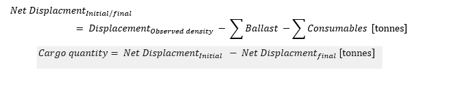
Briefly, the weight of the ship is determined both before and after loading/discharging and allowances made for all known deductibles. The difference between these two weights, known as net displacement , is the weight of the cargo loaded or discharged.
2. Draft survey methodology
2.1 Vessel’s condition
In order to prove accurate result of the draft survey the vessel has to comply with the following:
- To be upright in case not possible, the list must not be more than 0,5⁰;
- Minimum possible trim and in all cases, within the corrections covered in the ship’s tank sounding tables;
- Draft marks to be well visible, painted and its distance to the forward or aft perpendicular should be known;
- Means of access in order to check draft from seaside to be available;
- The vessel has to be provided with approved hydrostatic and tanks sounding tables;
- Minimum ballast tanks to be slack;
- All sounding pipes to be unobstructed and capable of serving their intended purpose;
2.2 Draft
The most essential part of each draft survey is the correct observation of all of the vessel’s drafts.
But as every experienced draft surveyor knows, the above is easy to be said and hard to be accomplished due to following factors:
- Due to the height of the jetty the present draft could not be seen horizontally or in some cases could not be seen at all.
- Draft marks are positioned under or in close proximity to jetty’s fenders.
- Ripples or waves in the port basin due to passing vessel, insufficient break water protection etc.
- Insufficient illumination during the night;
- Draft marks missing or in poor condition;
- Vessel’s rolling or pitching;
- Change of draft due to strong current;
- Change in draft due to thermal expansion of the vessel’s hull due to the solar heat radiation;
 |
 |
|
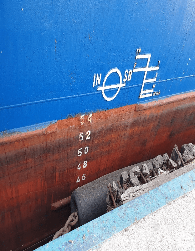
Figure 1. Typical draft mark
|
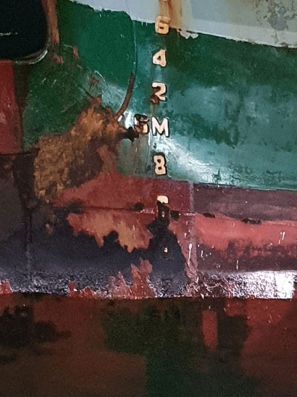
Figure 2. Draft mark in bad/unreadable condition
|
2.2.1 Correction of draft to perpendiculars
The hull volumetric characteristics are based on some theoretical lines and dimensions namely the forward, aft perpendicular, midship, moulded drafts, hull and water line coefficient etc.
During the vessel construction stage, the vessel’s draft marks are marked in a convenient position and are very often offset from the exact position of the forward, aft perpendicular or midship.
For calculations purposes, the drafts of the perpendiculars and midship are required so the observed drafts have to be corrected using the below formulas:
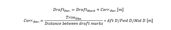
where:
DraftPer. – Corrected draft to the relevant perpendicular [m];
Draftmark – Observed draft from forward, mid, aft marks [m];
Corr.Per. – Correction of the draft from draft mark to perpendicular [m];
Trimobs. – Observed trim of the vessel [m];
Aft D – Distance from aft draft mark to aft perpendicular (If draft mark is aft from perpendicular the sign is “-” if forward “+”) [m];
Mid D – Distance to midship draft mark to midship of the vessel (If draft mark is aft from perpendicular the sign is “-” if forward “+”) [m];
Fwd D – Distance from forward draft mark to forward perpendicular (If draft mark is aft from perpendicular the sign is “-” if forward “+”) [m];
TrimObs. – Difference between forward and aft draft (aft trim is “+”, forward trim is ”-”);
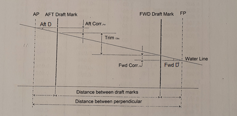
Figure 3. Draft Corrections
2.2.2 The Mean of the Means of the Mean draft
The shape of the vessel’s hull leads to an unbalanced distribution of cargo, ballast, lightship weights and buoyancy of the hull during the different loading condition, which creates deformations known as hogging and sagging. The Hogging effect is most common during ballast passage or partial loading, where the ship will deform as a beam supported at mid length and loaded at the ends. The Sagging is most common for loaded vessel and the hull will curved as a beam supported at the ends and loaded at mid length.
In order to compensate for the effect of the hull deformations and to determine the average midship draft, in the draft survey computation the following approximate mathematical method is used:

where:
DraftFwd – Corrected to forward perpendicular draft [m];
Draftmid – Corrected to vessel’s midship draft [m];
Draftaft – Corrected to aft perpendicular draft [m];
2.3 Displacement
2.3.1 Displacement at draft
Once the mean of the means of the mean draft is calculated, the relevant vessel’s displacement has to be extracted from the vessel’s hydrostatic tables. The vessel’s hydrostatic tables are based on the moulded draft, which is the draft corrected for the keel thickness, but some tables contained both moulded and external drafts.
Very often the exact draft couldn’t be found directly in the ship’s tables and interpolation, between the two closest drafts, has to be performed.
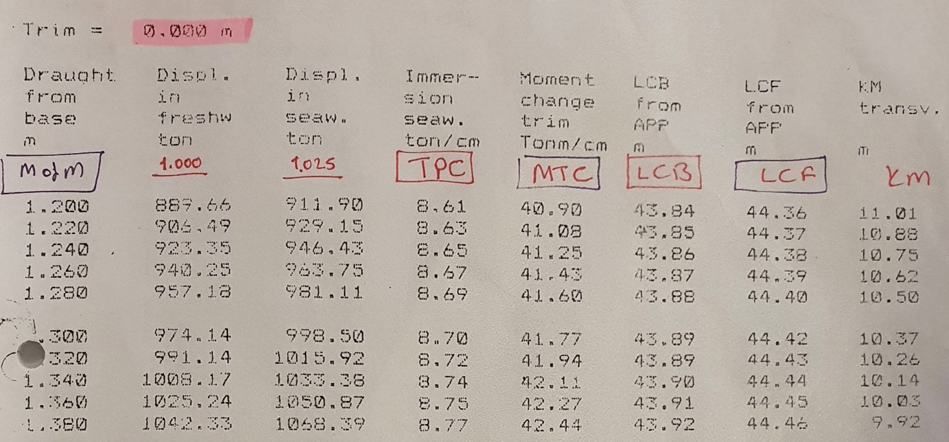 Figure 4. Typical extract from vessel’s hydrostatic tables
2.3.2 Displacement corrections
2.3.2.1 Trim correction
Due to the uneven shape of the vessel in forward and aft part, at constant average draft a vessel on even keel has bigger displacement than vessel with trim.
Most of the vessels have only one hydrostatic table for even keel and the displacement extracted from it, need to be additionally corrected for trim. In case the vessel’s hydrostatics cover various trim conditions, the exact displacement for actual trim can be found interpolating between the closest one.
2.3.2.1.1 1st correction (Layer Correction)
The physics behind the first correction is that actually the vessel’s is trimmed over a line passing though the Longitudinal center of floatation (LCF) and not about midship. The previously calculated mean draft is adjusted and corrected for midship, so in order to determine the true mean draft additional correction for the distance between LCF and midship section has to be performed.
This correction is similar by nature to the corrections of the draft from the draft mark to perpendiculars and is determined by the following formula:
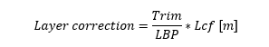
Where LCF is the distance between the vessel’s midship section and the longitudinal center of floatation. The LCF has to be extracted and interpolated from the hydrostatic tables for the calculated draft and assigned “+” if aft from midship and “-” if forward.
Considering the above the true mean draft is the mean of the means of the mean draft corrected with the layer correction.
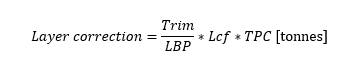
However, the normal draft survey calculation method corrects the extracted displacement apart from adjusting the draft. In this case the layer correction is calculated in tonnes using the following formula:
 2.3.2.1.2 2nd correction (Nemoto’s correction)
The position of the LCF, as specified in the hydrostatic tables, is for even keel condition. The longitudinal center of floatation is by nature the geometric center of the waterplane area. Once the vessel is trimmed, the waterplane area changes due to the non-symmetrical shape of the vessel’s forward and aft parts, which leads to a change in the LCF position. The 2nd trim correction aims to correct the displacement due to the misplacement of the LCF.
The 2nd trim correction is also calculated in tonnes using the following formula:
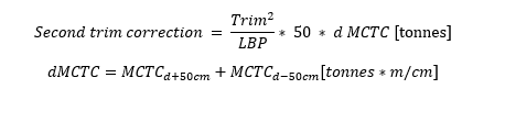 where:
d MCTC is the difference in Moment to change trim (MCTC) for 1 meter;
MCTCd+50cm is MCTC for mean adjusted draft + 50 cm;
MCTCd-50cm is MCTC for mean adjusted draft – 50 cm;
2.3.2.2. Seawater density
The final correction, which has to be utilized, is for adjusting the displacement for the water density, in which the vessel floats. The water density in different ocean regions around the globe varies widely. Therefore, the value of 1.025 tm/m3 has been recognized to be the average seawater density and most of the vessel’s hydrostatic tables are calculated for this standard density.
In order to perform accurate draft survey calculation, a sea water sample has to be taken and actual water density determined using draft survey hydrometer. After the displacement is corrected for trim, it has to be adjusted for the difference in densities using the following formula:

2.4 Ballast water
All ballast water tanks, even those said to be empty, must be carefully sounded or proven to be full by pressing up and overflowing from vent pipes. It is a good practice that the height of the measuring pipe of each ballast tank is noted and checked against the data in the vessel’s drawings/tables.
In order to avoid any mistakes in ballast calculations in case the ballast tanks don’t have a correction for the list, the vessel has to be upright, and if no trim correction available, tanks to be either full or empty.
The density of each ballast tank has to be known, the surveyor can check it in the last discharging port draft survey and/or as noted in the ballast logbook for previous ballast operations.
Calculation of the weight of ballast water is undoubtedly the most usual source of errors, which may result in very large and unacceptable inaccuracies in the cargo quantity.
2.5 Various consumables
In addition to the ballast all other tanks containing consumables like HFO, MDO, Lubrication oil, freshwater, or residuals like bilge, sludge, sewage, etc. have to be checked or quantities taken from the Chief Engineer records.
3. Cargo determination
As mentioned above the net displacements before and after loading/discharging have to be calculated and the difference between them is the cargo loaded/discharged.
The draft survey calculation can be cross-checked by the so-called vessel’s constant. The constant is determined during the surveys by deducting the lightship and the cargo as per the Bill of lading (B/L) from the Net Displacement. The constant includes all unknown weight like – stores and provisions, mud in the ballast tanks, marine growths on the hull, lightship changes, etc.
Considering the nature of the ship’s constant it can be considered permanent for a prolonged period of time and wide variations can be expected only after the vessel’s dry-docking or undergoing substantial repairs/modifications.
Comparing the calculated one with the constants, determined during previous draft surveys, will assist in determining any substantial inaccuracies during the draft survey.
References
United Nations Conference on Trade and Development. (2019). Review of maritime transport 2019. Geneva: United Nations.
United Nations Economic and Social Council . (1992). Code of uniform standards and procedures for the performance of draught survey of coal cargoes. United Nations.
Disclaimer: This post is not meant to be authoritative writing on the topic presented. thenavalarch bears no responsibility for the accuracy of this article, or for any incidents/losses arising due to the use of the information in this article in any operation. It is recommended to seek professional advice before executing any activity which draws on information mentioned in this post. All the figures, drawings, and pictures are property of thenavalarch except where indicated, and may not be copied or distributed without permission.
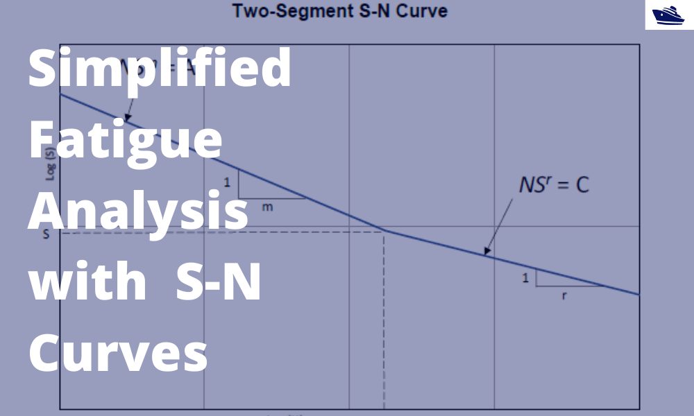
A simplified method of performing fatigue analysis of offshore structures
A simplified method of performing fatigue analysis of offshore structures Introduction An offshore structure is subject to environmental loads of waves, wind and current. By their nature, the resulting wave loads on the structure are cyclical. These cyclical...

How to use a ship’s hydrostatics to calculate its draft and trim
Introduction A ship’s hydrostatics, or hydrostats, is an oft used term in maritime parlance, and it refers to the characteristics when it is floating. What characteristics are these? How are these determined, and how can we read and understand them? Understanding...
Numerical integration methods for hull volume estimation
Introduction The hull of a ship is a complex 3D geometry, and finding out its simple properties like volume, centroid, etc. is not possible through simple formulae unlike standard shapes like cuboid or a cylinder. How do we find a property, say the volume of a...
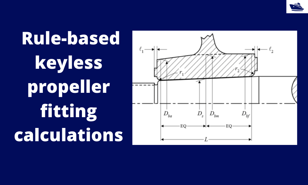
How to do rule-based fitting calculations of a keyless propeller
Introduction A keyless propeller, as the name implies, requires no key for fastening the propeller on the cone of the propeller shaft. How is the torque then transferred to the propeller? The torque is transferred by the friction between the propeller and the...

Designing Fillet Welds for Symmetrical Joint Sections
Introduction Fillet welds are the most commonly used weld types in marine structures. A fillet weld is used when there are two pieces of metal that are joined perpendicular to each other or at an angle. In this article, we will explore how to select the right size...
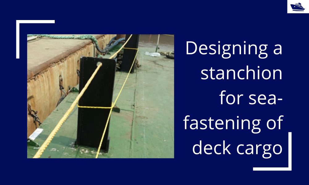
Designing a stanchion/stopper for sea-fastening of deck cargo
Introduction Stanchions – a familiar term for mariners and ship designers. What are Stanchions? A stanchion is generally a vertical pipe or beam which is used to support some structural item or provide support rails on the deck. In ships, the most common type of...
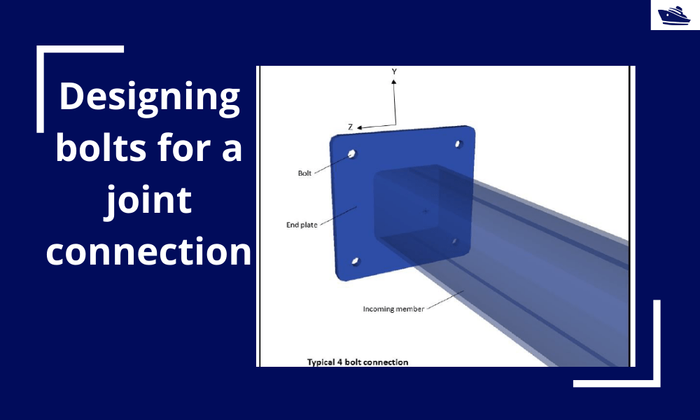
Designing bolts for a joint connection
Introduction Bolts are very commonly used fastening items and used in a variety of configurations. In this article, we will explore in-depth the design of a bolt used in connecting two members at a joint (bolted joint). We'll see what properties of the bolt are...
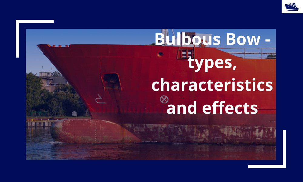
The Bulbous Bow – types, characteristics, and effects
This is Part 2 of the two-part series on Bulbous Bows. For Part 1, click here By Tamal Mukherjee, *This article originally appeared in May 2019 edition of Marine Engineers Review (India), the Journal of Institute of Marine Engineers India. It is being...
Using Class Rules to assess the Longitudinal Strength requirement of Barges
Introduction The longitudinal strength of a vessel is integral to its evaluation for a given purpose. To get an introduction to the topic, please refer to our other article https://thenavalarch.com/longitudinal-strength-ships-introduction/ In this article, we’ll see...
The why and how of freeboard calculation of a ship
Introduction Freeboard is a common term used in vessel operations. Freeboard is the smallest vertical distance between the waterline and the freeboard deck (generally the upper deck) along the length of the vessel. The term ‘smallest’ is of significance, as the height...
excellent
Thank you
Thanks for sharing
Thanks for sharing.
Based on my observations whilst conducting draft surveys alongside surveyors representing other interested parties on bulk carriers, I now disregard the historical records of previous draft surveys. This is primarily because there is a tendency for ship’s officers and surveyors to simply adjust the ballast, density, FW or even the draft readings to agree with the B/L in the case of cargo discharged or the vessels declared constant prior to loading.