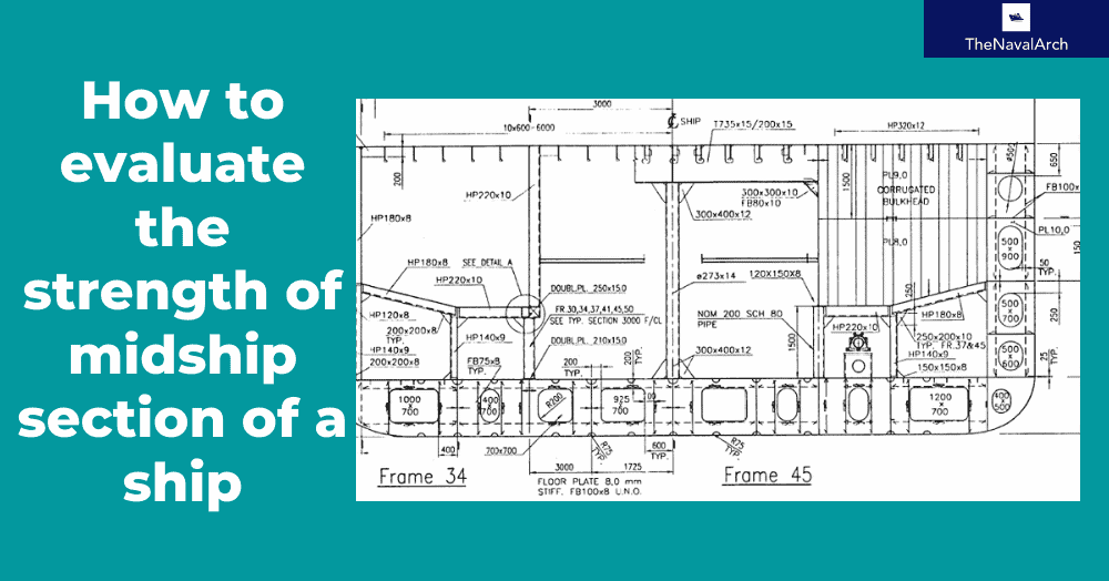
The mid-ship section of a ship is a defining structural drawing of the vessel. It represents the most critical structural parameter of the vessel – its global strength. To assess how much of the bending moment (hog and sag) the vessel can tolerate, it is important to assess the structural strength of the mid-ship section as a whole.
The bending stress experienced by the midship section of the vessel is calculated from the standard bending stress formula
Bending Stress = Bending Moment/Section Modulus
Here, the bending moment is calculated from a detailed procedure as described in our other article – Longitudinal Strength for Ships.
Beam analogy
Now we focus on the other parameter – Section Modulus. What is section modulus?
If we look into a simple beam that is bending under a load, section modulus is a geometric property of the beam’s cross-section which is also a direct measure of the beam’s strength under the bending load.
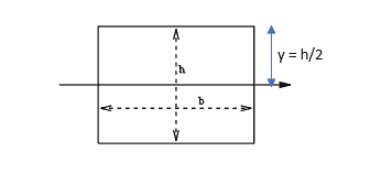
Looking at a beam of width b and thickness h, the section modulus for bending about the horizontal axis through its centroid tis given by
Z = bh2/6
Basically, the formula for Section Modulus of a beam is Z = I/Yext, where I is the geometric moment of inertia of the beam about the horizontal axis passing through its centroid and is given by
I = bh3/12
‘Yext’ is the distance of the neutral axis of the beam to the topmost point in the beam’s section, and Yext = h/2 (see figure below)
Beam analogy: Midship Section
Extrapolating to a ship
The ship’s longitudinal strength is assessed by taking it analogous to a simply supported beam. The ship is subject to loads of weight and buoyancy, and the net load distribution along the length is used to give the shear force and bending moment distribution along the length. Please read our article on longitudinal strength for more.
Applying the same principle to a ship, the bending stress of the ship at its midship will be given by:
Bending Stress = Bending Moment at midship/Section modulus of Midship
What does the ‘Section Modulus’ of midship mean? Looking at the typical structural section of a ship, it looks like this:
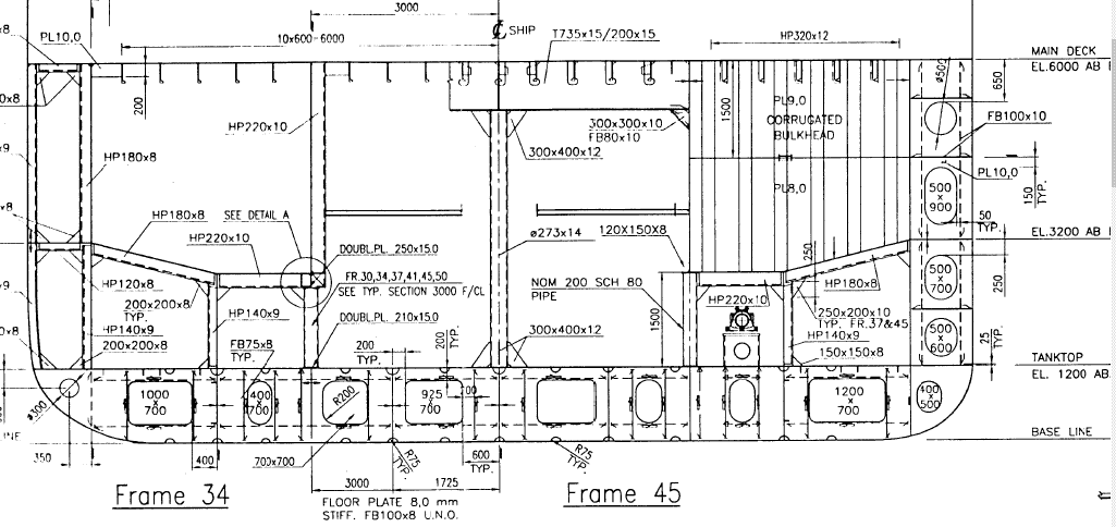
A Midship Section Drawing
How do we conceive of it as a beam? A beam has a solid cross-section, while the midship section has multiple structural members, with most part hollow. These structural members are plates, stiffeners, girders, frames, etc. For section modulus calculation, only longitudinal members are considered (plates stiffeners, girders, etc which run along the length of the vessel), and transverse members like frames are not included. The section modulus of the entire midship section is an aggregate of the section moduli of all the longitudinal strength members. Thus, the keel plate may comprise multiple strakes, and each strake contributes its own to the final section modulus of the entire section.
Moment of Inertia Calculation
Since section modulus is calculated from the moment of inertia, let’s take a look at the moment of inertia. The moment of inertia is a property of a body that determines how much moment is required for it to bend about an axis. Obviously, the further the body is from the axis of rotation, the more the torque required, and thus higher is the moment of inertia.
That also means that if the axis is passing through the center of the body itself, the moment of inertia will be the least.
The moment of inertia of any component in the midship section is given by:
ITOT = ISELF + A x (y – yNA)2
Where ITOT is the total moment of inertia of the body, ISELF is the moment of inertia of the body about its center of mass, A is the section area of the body, while (y – yNA) is the distance of the body’s center of mass from the neutral axis of the midship section. See figure below:
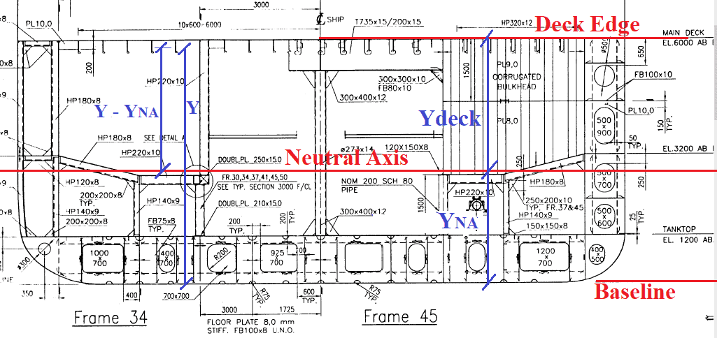
Midship Section – Neutral Axis and Baseline
A few questions arise:
- Where is the neutral axis of the midship section? How is ‘A’ calculated?
- From where are y and yNA being measured?
y and yNA are measured form a reference axis, and yNA is calculated from the section areas of different members.
The formula for yNA is
yNA = ΣAi*yi/ΣAi
Here, ‘i’ is the ith structural member in the midship section. Ai is the section area of the ith member, and yi is the distance of the centroid of the ith member from the reference axis. Which axis to choose as a reference axis? Generally, the base of the midship (the keel) is selected as a baseline (see figure above).
Now we go back to the formula for ITOT. Once we have calculated the neutral axis location, we can calculate the ITOT for each item individually.
Calculation of self-moment-of-inertia
The self-moment of inertia for each item can be calculated by taking into account the geometry of the item, and its orientation.
For a plate of dimensions b x t, where its width is ‘b’ and its thickness is ‘t’, the self-moment of inertia is calculated about an axis which passes through its own centroid and is parallel to the baseline. Hence, if the plate is orientated completely horizontally, the formula is
ISELF = bt3/12
while for a vertically orientated plate, the formula is
ISELF = tb3/12
For a plate which is inclined at an angle, the
ISELF = bt(b2sin2α + t2 cos2α)/12
These are demonstrated in the figure below:
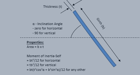
Inclined plate moment of inertia
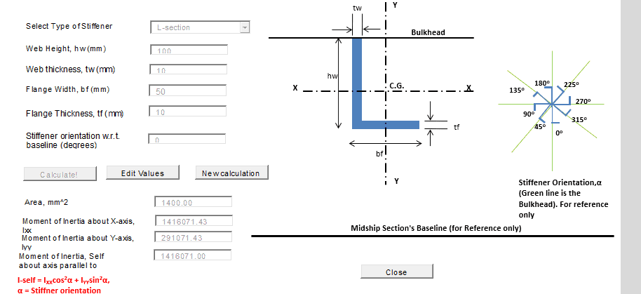
Similarly, for stiffeners, the self-moment-of-inertia will depend upon the type of stiffener (L, T or bulb) and also its orientation w.r.t. the baseline. A simple calculator can be developed for calculating the self-moment-of-inertia of a stiffener. This will calculate the individual contributions of the web and flange and aggregate them to provide the final values for the stiffener. A calculator developed by TheNavalArch looks like the below:
Summing it up for the whole midship section
Once we’re able to calculate the contributions of each individual section, it is time to put their contributions together to calculate the properties of the entire midship section as a whole. This can be done in a simple manner by adding all the items and their properties/contributions with the applicable formulas into a spreadsheet, which may look something like this:
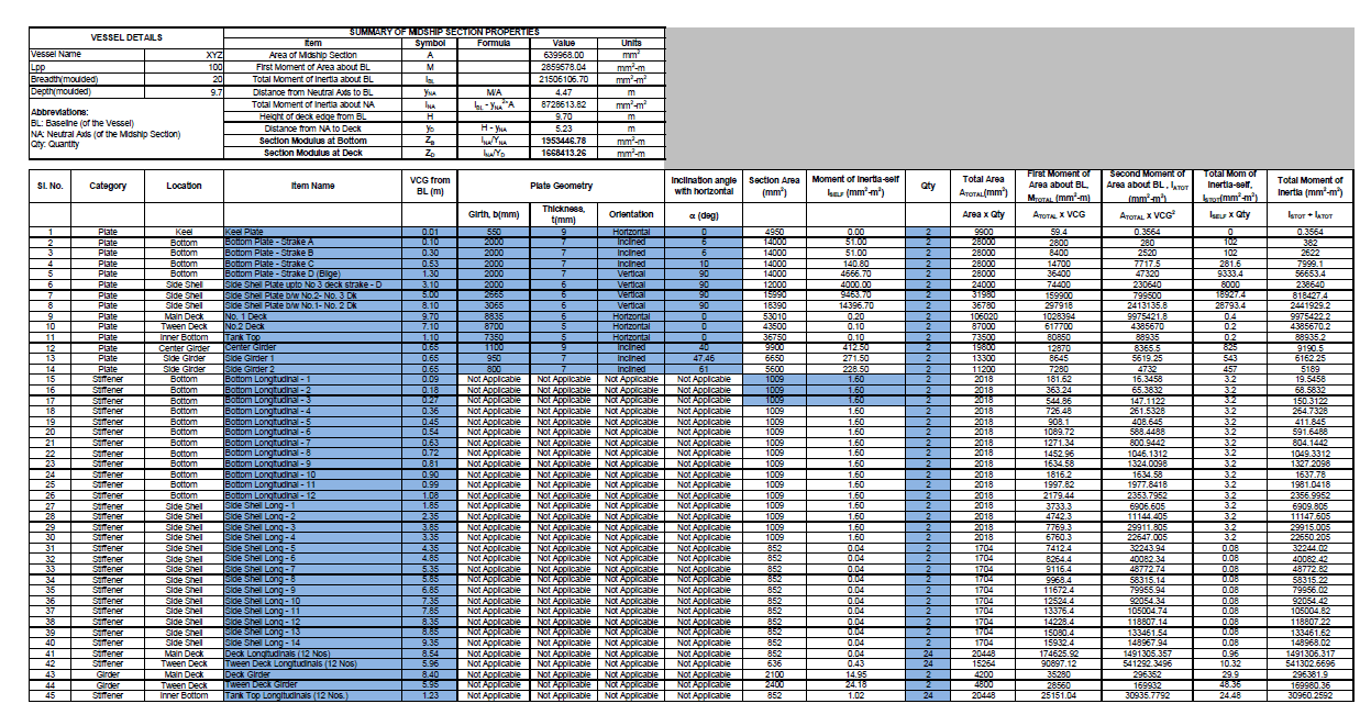 Sample Calculation of Midship Section Modulus
We can see that there are multiple members listed above, and section area and moment of inertia (self and about the baseline) are being calculated for each. Their section areas are summed up to give the section area for the whole section. Similarly, their moments of inertia are also summed up to give the moment of inertia for the whole section about the Baseline of the midship section (IBL). The first moment of area ΣAi*yi is calculated and divided by the total area to give the neutral axis location YNA.
Now we move to the calculation of the Section Modulus of the entire section. The section modulus at any location is given by
Section Modulus = INA/yLOC
Here, INA is the moment of inertia of the midship section about the neutral axis (i.e., horizontal axis passing through the centroid of the midship section), and is given by
INA = IBL – yNA2 x A
Also, yLOC is the vertical distance (absolute) of the location under consideration from the neutral axis of the midship section.
Since the bending stress is inversely proportional to the Section Modulus, the location of the midship section which has the lowest section modulus will be expected to have the maximum bending stress. Again, since section modulus is inversely proportional to the distance of the location to the neutral axis, the location which is furthest from the neutral axis will be expected to have the lowest section modulus.
This location is usually on the deck, or on the baseline. If the height of the deck edge from Baseline is H, then the distance of the deck edge from the neutral axis is given by
yD = H – yNA
Section Modulus at the Baseline and at the deck will be given by the following formulae:
ZDECK = INA/yD, ZBASELINE = INA/yNA
The lower of ZDECK and ZBASELINE should be used to calculate the bending stress on the midship section.
That brings us to the end of this article. Please do take a moment to check-out TheNavalArch’s own excel-based app to calculate Midship Section Modulus.
References
- https://en.wikipedia.org/wiki/Section_modulus
- Principles of Naval Architecture, Vol I
Disclaimer: This post is not meant to be authoritative writing on the topic presented. thenavalarch bears no responsibility for the accuracy of this article, or for any incidents/losses arising due to the use of the information in this article in any operation. It is recommended to seek professional advice before executing any activity which draws on information mentioned in this post. All the figures, drawings, and pictures are property of thenavalarch except where indicated, and may not be copied or distributed without permission.

Getting the right thickness of GRP laminate for your boats
Introduction GRP laminates are widely used in the fabrication of high-speed crafts and light crafts/boats globally. GRP stands for Glass Reinforced Plastic. As the name suggests, GRP contains glass fibers embedded into a plastic resin. This gives it higher strength,...
Designing Fillet Welds for Symmetrical Joint Sections
Introduction Fillet welds are the most commonly used weld types in marine structures. A fillet weld is used when there are two pieces of metal that are joined perpendicular to each other or at an angle. In this article, we will explore how to select the right size...
Designing a stanchion/stopper for sea-fastening of deck cargo
Introduction Stanchions – a familiar term for mariners and ship designers. What are Stanchions? A stanchion is generally a vertical pipe or beam which is used to support some structural item or provide support rails on the deck. In ships, the most common type of...

Hydrogen as an alternative fuel for ships to reduce emissions
,This article first appeared in the Feb 2019 edition of Marine Engineers Review. It is being reproduced with minor edits here for the readers of TheNavalArch's blog. Introduction The world is on facing a grave environmental challenge with an increase in carbon...

Global wave statistical analysis and its use in deepwater operations
Why do we need wave analysis? For the design of offshore operations such as installation and transport of offshore structures, as well as lifecycle design of floating and fixed structures, knowledge of extreme waves as well as the probability of different sea-states...
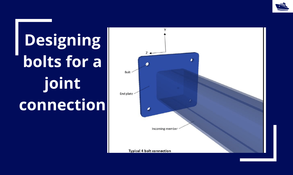
Designing bolts for a joint connection
Introduction Bolts are very commonly used fastening items and used in a variety of configurations. In this article, we will explore in-depth the design of a bolt used in connecting two members at a joint (bolted joint). We'll see what properties of the bolt are...
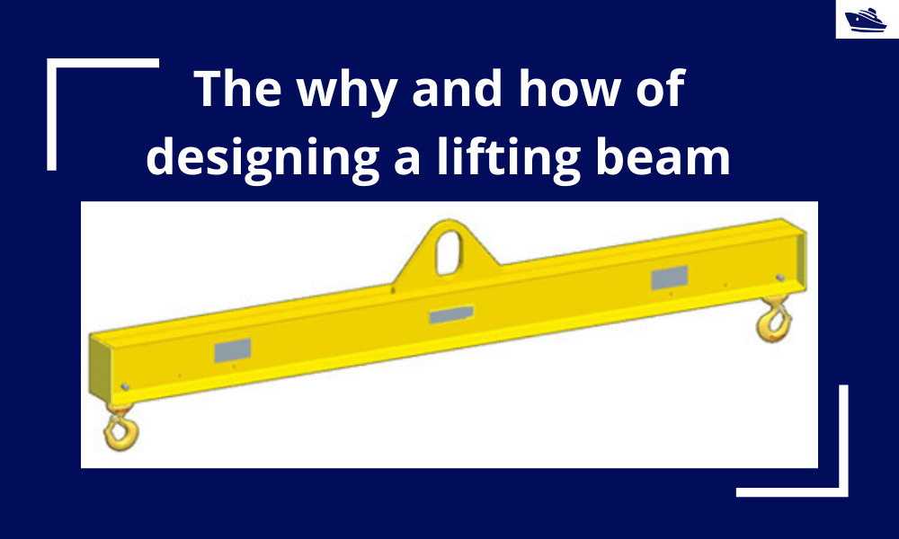
The why and how of designing a lifting beam
Lifting beams are universally applied gear used widely in various types of lifting operations, onshore and offshore. In this article, we will explore the design of a basic lifting beam and see what design checks are needed to establish the suitability of the beam for...
Draft Surveys: Methodology, Calculations, and common errors
Introduction Marine transport is the backbone of the global trade and reasonably can be considered to be the artery of the global manufacturing supply chain, as more than four fifths of the world merchandise trade by volume is carried by sea. Undoubtfully, the...
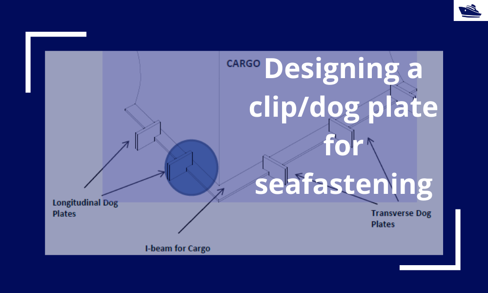
Designing a clip/dog plate for seafastening
Introduction In an earlier article, we saw how to design stoppers for seafastening. Stoppers are items that are used to contain the translation movements (longitudinal and transverse directions) of a cargo on the deck/hold of a vessel. That brings us to the question –...
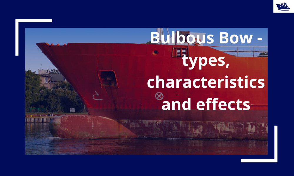
The Bulbous Bow – types, characteristics, and effects
This is Part 2 of the two-part series on Bulbous Bows. For Part 1, click here By Tamal Mukherjee, *This article originally appeared in May 2019 edition of Marine Engineers Review (India), the Journal of Institute of Marine Engineers India. It is being...

k
I am a Marine Engineering lectural