Introduction
A keyless propeller, as the name implies, requires no key for fastening the propeller on the cone of the propeller shaft. How is the torque then transferred to the propeller? The torque is transferred by the friction between the propeller and the propeller shaft.
In this article, we’ll see what important parameters govern the design of a keyless propeller, and how these can be calculated.
These are based on ABS Rules for Building and Classing Steel Vessels 2019, Part 4 Vessel systems and machinery, Section 3 Propellers. Class rules require a minimum factor of safety against the slip of 2.8, which can be used to calculate the maximum pull-up load. This load also depends on several other parameters like the type of propulsion, diameters of boss and hub, rated thrust, etc. that have been discussed below.
Design Parameters
The following design parameters are important for the keyless propeller design:
- Minimum required mating surface pressure
- Minimum pull-up length
- Pull-up Load
- Dry-fitting
- Wet-fitting
- Contact surface pressure
- Hoop stress
- Equivalent stress
Parameters like mating surface pressure and pull-up length also depend on the temperature of operation.
Design Criteria
The design criteria as per ABS rules are as follows:
- The factor of safety against the slip of the propeller hub on the tail shaft taper at 35°C (95°F) is to be at least 2.8 under the action of maximum continuous ahead rated torque plus torque due to torsional vibrations.
- The maximum equivalent uniaxial stress (von Mises-Hencky criteria) in the hub at 0°C (32°F) is not to exceed 70% of the minimum specified yield stress or 0.2% proof stress of the propeller material.
- The calculations submitted must cover the following parameters:
- Theoretical contact surface area
- The maximum permissible pull-up length at 0°C (32°F) as limited by the maximum permissible uniaxial stress specified above
- The minimum pull-up length and contact pressure at 35°C (95°F) to attain a safety factor against slip of 2.8
- The proposed pull-up length and contact pressure at the fitting temperature
- The rated propeller ahead thrust
Inputs
The calculations will require multiple inputs related to the propeller’s geometry and material, along with the vessel’s parameters like speed.
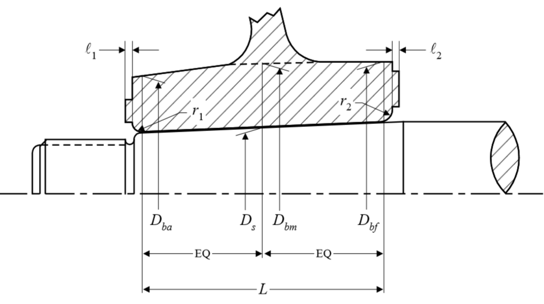
The inputs all follow the rule requirements by ABS, and are listed below. The diagram below also depicts some of the inputs.
- Contact surface area between propeller hub and shaft taper (A)
- Coefficient of friction between mating surfaces (µ)
- Half taper of shaft (θ)
- Factor of safety against slippage at 35°C (S)
- Coefficient for type of propulsion drive (c)
- Outer diameter of hub corresponding to Ds (Dbm)
- Outer diameter of hub corresponding to the forward point of contact (Dbf)
- Outer diameter of hub corresponding to the aft point of contact (Dba)
- Mean outer diameter of hub corresponding to Ds (Db)
- Diameter of shaft at mid-point of the taper in axial direction (Ds)
- Mean propeller pitch (P)
- Rated propeller thrust
- Calculated based on Power at rated speed (H), Vessel speed at rated power (v), and Rpm at rated speed (R), OR
- from designer (T-User)
- Modulus of elasticity of hub material (Eb)
- Poisson’s ratio of hub material (νb)
- Coefficient of linear expansion of propeller hub material (αb)
- Modulus of elasticity of shaft material (Es)
- Poisson’s ratio of shaft material (νs)
- Coefficient of linear expansion of shaft material (αs)
- Yield stress or 0.2% proof stress of propeller material (σy)
- Reference temperature as per rule (tref)
- Contact length (L)
Calculations
The formulations for the various parameters are shown below:
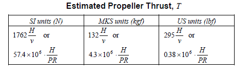
- Rated propeller thrust – if the designer has this value, then the designer’s value is used, else the value from rules can be used
- Rated Torque – Q is the rated torque which is an input corresponding to H & R, however, it can be estimated from the formula below
![]()
- Shear force at the propeller-shaft interface

- Pull-up length
The minimum pull-up length is taken at 35 degrees C, and is given by

The minimum pull-up length at any other temperature (less than 35 degrees) is given by

- Minimum mating surface pressure at 35 degrees C is given by
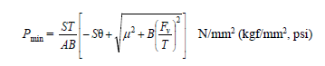
The minimum mating surface pressure varies with temperature, and at another temperature less than 35 degrees C, it is given by

Here δmin and δt are the pull-up lengths at 35 deg and at temperature ‘t’ respectively.
- Pull-up load
The pull-up load can be calculated using the formula below:
Wt (pull-up load) = A x Pt (μ + θ), where
μ = coefficient of friction between mating surfaces. For wet fitting, the friction is considerably lower than dry fitting
θ = Half taper of shaft
- Stresses: The hoop stress and equivalent stress can be given by:
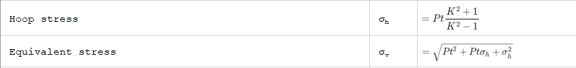
where K is the ratio of Db and Ds
That brings us to the end of this article. TheNavalArch also has its own product which simplifies the above calculations for the user. Please do check it out
References
- ABS Rules for Building and Classing Steel Vessels 2019 , Part 4 Vessel systems and machinery, Section 3 Propellers
- https://trid.trb.org/view/63325
Disclaimer: This post is not meant to be authoritative writing on the topic presented. thenavalarch bears no responsibility for the accuracy of this article, or for any incidents/losses arising due to the use of the information in this article in any operation. It is recommended to seek professional advice before executing any activity which draws on information mentioned in this post. All the figures, drawings, and pictures are property of thenavalarch except where indicated, and may not be copied or distributed without permission.
https://thenavalarch.com/software/maritime-industry-thenavalarch/ship-design/resistance-propulsion/keyless-propeller-fitting-calculations/
Designing the lashings of deck cargo using IMO CSS
Introduction More than 70% of the earth is covered by water, which makes shipping historically the easiest and cheapest way of connecting manufactures and customers across the globe and can be reasonably considered to be the artery of the global economy....

Using MS Excel to evaluate the Stability of existing Barges
Barges are the simplest, and yet most widely used of marine vehicles. They are used for a variety of purposes ranging from carrying cargo in bulk or liquid, to even carrying passengers for short inland cruises. Barges are mostly towed by another barge called a tug,...
The importance of ULS (Ultimate Longitudinal Strength) and how to assess it for a damaged hull
by Alessandro La Ferlita, Naval Architect Ultimate hull girder strength represents the maximum capacity, of the hull girder beyond the structure fails. In fact, if the vertical bending moment applied overcomes a certain maximum value, the ship can collapse (Figure 1)...
How to calculate the strength of Midship Section of a Ship
The mid-ship section of a ship is a defining structural drawing of the vessel. It represents the most critical structural parameter of the vessel – its global strength. To assess how much of the bending moment (hog and sag) the vessel can tolerate, it is important to...
How to use empirical formulas to estimate the resistance of a Ship
How to use empirical formulas to estimate the resistance of a Ship Resistance estimation holds immense importance in the design stage of a vessel. Based on the results of the resistance estimation of a vessel, the selection of the right propulsion system is done....
Designing the berth mooring of your vessel with this simple yet effective method
A vessel at berth experiences much lower forces compared to a vessel in the open sea due to the milder environment, but it still requires a mooring configuration suited to the forces it experiences, and also suitable for the type of berthing configuration adopted. The...

Bulbous Bows – History and Design
by Bijit Sarkar, Naval Architect Introduction The eternal search of a naval architect – a perfect bow. Sadly, it never exists. Different bow forms are good for different types, sizes of vessels and seaways. What does a naval architect want out of the bow he designs?...
Understanding how buoys affect the catenary of a mooring line
What is a mooring line? Mooring lines generally comprise ropes, wires, chains or combination of wire and chain used to keep ships, offshore platforms and other floating vessels in position. It connects the structure either to the seabed using an anchor or the quay...
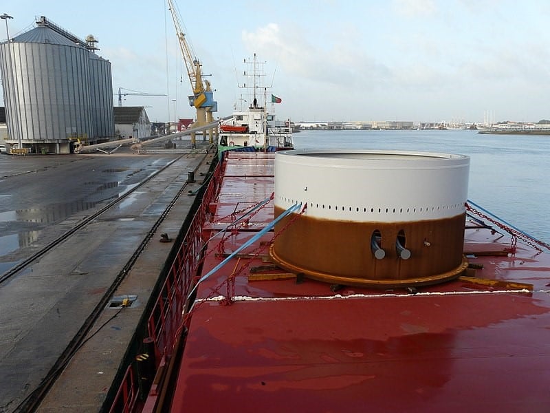
Calculating forces on a ship’s deck cargo – a simplified approach
A cylindrical deck cargo (Source: Wikimedia) Introduction A ship’s deck is used to transport many different types of cargo – from containers to large structures like cranes or heavy modules of an offshore production plant. During transport, the ship suffers from...
Designing a pad-eye: little items with big intricacies
Pad-eyes are one of the smallest and most universally used structural items in the maritime and Oil & Gas industry. They are used for a variety of purposes too: from a simple seafastening of a cargo to deck of a vessel, to complicated lifting operations involving...
