Introduction
A ship’s hydrostatics, or hydrostats, is an oft used term in maritime parlance, and it refers to the characteristics when it is floating. What characteristics are these? How are these determined, and how can we read and understand them? Understanding hydrostatics helps in many ways, viz
- We can find out the floating draft and trim and many other hydrostatic parameters of a ship by knowing hydrostatics, without having to physically measure them
- A preliminary evaluation of the stability of the ship can be made by looking at the hydrostatics
As a vessel is loaded, the draft and trim of the vessel keep changing with the weight and location of the loads. Loads can be cargo, passengers, fuel, ballast, etc. and these keep varying during the voyage of the vessel.
If I were to fill the tanks with a certain %age filling, add cargo to holds, and ballast the vessel to a given arrangement, how do I know what draft and trim the vessel stands at? Of course, measuring the drafts physically every time is not practicable. The simple way is to use the table of hydrostatics. In this article, we’ll discuss what hydrostatics are and how to use them to calculate the draft and trim of the vessel.
Hydrostatic Properties – Draft
What are some of the key hydrostatic properties that one may be interested in?
The water level at which the ship is floating is called the ‘draft’ of the vessel. Also, if we load the vessel so that the weight of the forward part of the vessel is higher than that of the aft part (e.g., loading the forward holds more), then the forward part of the vessel will sink more compared to the aft, leading to the water level (draft) in the forward to be more than that in the aft. This tilt is called ‘trim’ of the vessel, and it is measured by the difference in drafts in the forward and aft ends of the vessel.
Let’s start with a simple exercise of finding out the draft and trim.
- Step 1 – Finding out the Weight and Center of Gravity (CoG) – We begin with the weights on the ship, and the center of gravity of the weights. Following are the weights we need to account for:
- Self-weight of the ship excluding all fillings in tanks – this is called the lightweight of the ship. This is obtained from the inclining experiment of the ship which is a one-time exercise to yield the weight and center of gravity of the self-weight of the ship
- Weights in tanks – fuel, cargo, bilge, ballast, crew and provisions etc. These are together termed as ‘deadweight’
- Once we know the lightweight of the ship (from inclining experiment) together with the deadweight items, we can tabulate all the weight items and their individual CoG’s and then calculate the total weight and CoG of the entire vessel in the above ‘loading condition’
- Step 2 – Once we have the weight and CoG of the vessel in the given loading condition, the next step is to open the table of hydrostatics of the vessel and read the draft from there.
A table of hydrostatics will look like the below:
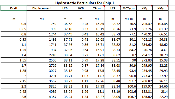
We can see that the first column is the draft spaced at equal intervals (in this case the interval is 0.15 m).
The second column is displacement. Once we have calculated the weight of the vessel in Step 1, that weight becomes the displacement. Thus,
* The hydrostatics table is for a given trim. Generally, the hydrostatics available are for the zero-trim condition, and the same are used to demonstrate the calculation in this article.
*Displacement = weight of the vessel in the floating condition (including deadweight)
Now, to read the draft, we need to look up the corresponding draft for the displacement value calculated in Step 1.
For example, if the displacement calculated was 1994 MT, then the draft is 1.25 m, and if the displacement was 2249 MT, then the draft will be 1.4 m.
However, what if the displacement calculated falls in-between two values listed in the hydrostatic table, say, 2220 MT?
In that case, we can find the draft by linear interpolation. For the above case, the displacement of 2220 MT falls between the displacement values 1994 MT and 2249 MT in the table. These displacements and their corresponding drafts are specified below:
| Displacement | Draft |
| D1 = 1994 | T1 = 1.25 |
| D2 = 2249 | T2 = 1.4 |
| D = 2240 | T = ? |
The interpolation formula is
T = T1 + (D – D1)/(D2 – D1) * (T2 – T1)
Which gives
T, draft at 2240 MT displacement = 1.25 + (2240 – 1994)/(2249 – 1994) x (1.4 – 1.25)
- T = 1.394 m
So, we have computed the draft from the hydrostatics table. However, this draft is measured at the LCF (Longitudinal Center of Floatation) of the vessel which is close to the midship and is also called the mean draft. The drafts at the two ends of the vessel may vary depending on whether the vessel experiences a trim too. To get accurate drafts at the ends of the vessel, we need to find out the trim of the vessel too. Let’s see how to get it from the hydrostats.
Hydrostatic Properties – Trim
The Trim of a vessel is the angle by which the ship tilts in a loading condition relative to its baseline. If the waterline is not parallel to the baseline of the vessel, then the vessel trims. The value of trim depends on how the vessel is loaded. If the aft of the vessel is heavier, then the draft at aft will be higher, and the vessel is said to ‘trim by aft’. Similarly, if the weight of the forward is higher, it ‘trims by forward’.
What causes the trim? If we look at the picture below, it shows the two fundamental forces acting on the ship: 1) The ship’s own weight acting downwards 2) The buoyancy of the submerged part of the ship. The vessel will not experience any trim if the two forces are acting along the same vertical at the same location along the vessel’s length. What happens if they are not acting at the same location but separated apart?
Looking at the figure below, the upward buoyancy force and the downwards weight force will lead to a turning moment on the ship. This ‘trimming’ moment will tend to tilt the ship till the weight and buoyancy forces align.
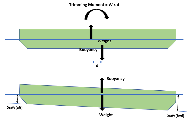
We can see that in the final condition the draft at fwd is more than the draft at the aft.
The trim is given by the difference in the drafts fwd and aft. In the above case, it will be ‘trim by fwd’.
In degrees, the trim is given by
Trim (degrees) = tan-1[(draft fwd – draft aft)/Length of ship]
Calculating Trim
We can see that we need the forward and aft drafts to calculate the trim. However, the draft available for us from the hydrostatic table is the draft at LCF (around midship). How do we calculate the trim then?
Any trim is caused by a trimming moment. As highlighted earlier, this trimming moment equals the Displacement of the vessel multiplied by the longitudinal distance between the Center of Gravity and Center of Buoyancy.
Trimming moment = Displacement x (LCG – LCB)
When the LCG is forward of the LCB, then the vessel trims by fwd, and when the LCG is aft of the LCB, then the vessel trims by aft.
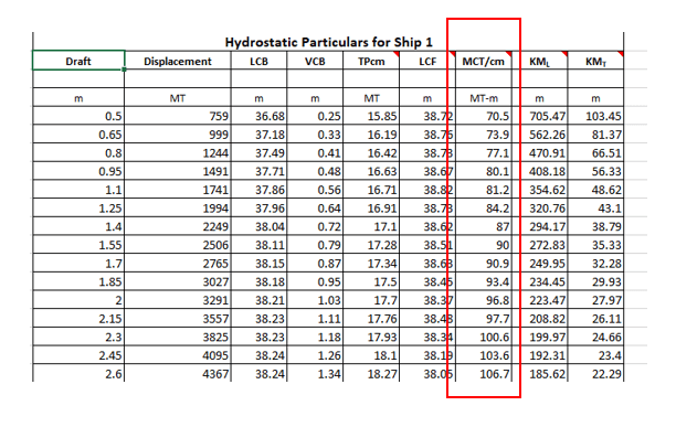
Once we have the trimming moment, the next step is to look at the hydrostatic parameter called Moment to Change Trim by 1 cm (MCTcm).
If we look at hydrostats again, we can see that there is a parameter called the Moment to Change Trim by 1 cm, called MCTcm. It is measured in the units of MT-m. Basically, to trim the vessel by 1 cm (where 1 cm is the difference in the drafts aft and fwd) we need to apply an overturning moment on the vessel. This moment depends on the waterplane of the draft at which the vessel is floating (the detailed calculation of MCTcm is out of the purview of this article).
The trim can be calculated by dividing the trimming moment by the MCTcm. This will give the total trim in cm.
Let’s look at an example. If the vessel is floating at, say, 1.1 m draft, then the following are the hydrostats:
- Displacement = 1741 MT
- LCB – the longitudinal center of buoyancy = 37.86 m. In this table, LCB is measured from the aft of the vessel, positive forward. The LCB measurement can be from other locations like midship or fwd end too.
- MCTcm = 81.2 MT-m
Now, we take two scenarios, depending on the location of the LCG:
- Case 1 – when LCG is fwd of LCB, say at 40 m from the aft of the vessel. In this case, the trimming moment is
Trimming moment = 1741 x (40 -37.86) = 3725.74 MT-m by FWD
Thus, the trim is
Trim = 3725.74/MCTcm = 3725.4/81.2 cm = 45.88 cm by FWD
Thus, the vessel is trimming by forward by 45.88 cm. This means that the difference between the drafts fwd and aft is 45.88 cm.
- Case 2 – when LCG is aft of LCB, say at 35 m from the aft of the vessel. In this case, the trimming moment is
Trimming moment = 1741 (Displacement) x (37.86 – 35) = 4979.26 MT-m by AFT
Thus, the trim is
Trim = 4979.26/MCTcm = 3725.4/81.2 cm = 61.32 cm by AFT
Thus, the vessel is trimming by aft by 61.32 cm. This means that the difference between the drafts aft and fwd is 61.32 cm.
Calculating the drafts aft and fwd from trim
Now we have the total trim, i.e., the difference between the drafts at aft and fwd. We also have the mean draft of the vessel which we obtained from the hydrostatics table. How do we get the drafts at the aft and fwd of the vessel?
As specified earlier, the draft measured is at the location of the LCF of the vessel. The following picture depicts the mean draft and the total trim of the vessel. We can see that the total trim is t = tf – ta which is measured over the length between perpendiculars (LBP) of the vessel.

Calculating backward, we can get the following relations:
ta = tm – LCF/LBP x t
tf = tm + (LBP – LCF)/LBP x t
That was about calculating the draft and trim of a vessel from its hydrostats. This can be helpful for quick evaluations of the floating position of the vessel when it is loaded.
Disclaimer: This post is not meant to be authoritative writing on the topic presented. thenavalarch bears no responsibility for the accuracy of this article, or for any incidents/losses arising due to the use of the information in this article in any operation. It is recommended to seek professional advice before executing any activity which draws on information mentioned in this post. All the figures, drawings, and pictures are property of thenavalarch except where indicated, and may not be copied or distributed without permission.
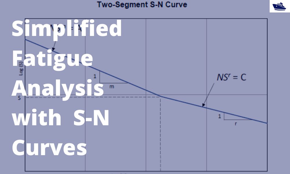
A simplified method of performing fatigue analysis of offshore structures
A simplified method of performing fatigue analysis of offshore structures Introduction An offshore structure is subject to environmental loads of waves, wind and current. By their nature, the resulting wave loads on the structure are cyclical. These cyclical...
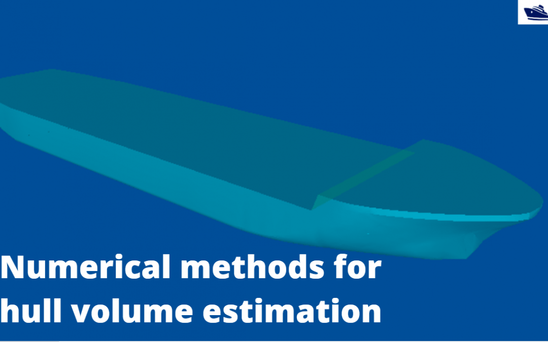
Numerical integration methods for hull volume estimation
Introduction The hull of a ship is a complex 3D geometry, and finding out its simple properties like volume, centroid, etc. is not possible through simple formulae unlike standard shapes like cuboid or a cylinder. How do we find a property, say the volume of a...
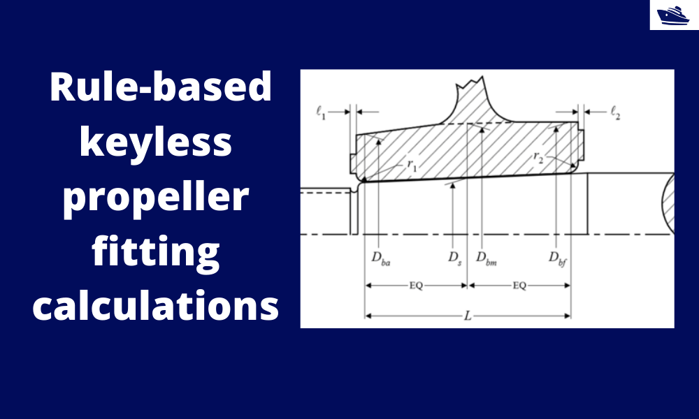
How to do rule-based fitting calculations of a keyless propeller
Introduction A keyless propeller, as the name implies, requires no key for fastening the propeller on the cone of the propeller shaft. How is the torque then transferred to the propeller? The torque is transferred by the friction between the propeller and the...
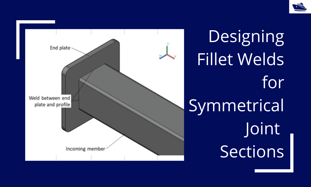
Designing Fillet Welds for Symmetrical Joint Sections
Introduction Fillet welds are the most commonly used weld types in marine structures. A fillet weld is used when there are two pieces of metal that are joined perpendicular to each other or at an angle. In this article, we will explore how to select the right size...
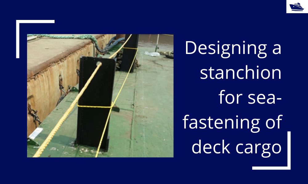
Designing a stanchion/stopper for sea-fastening of deck cargo
Introduction Stanchions – a familiar term for mariners and ship designers. What are Stanchions? A stanchion is generally a vertical pipe or beam which is used to support some structural item or provide support rails on the deck. In ships, the most common type of...
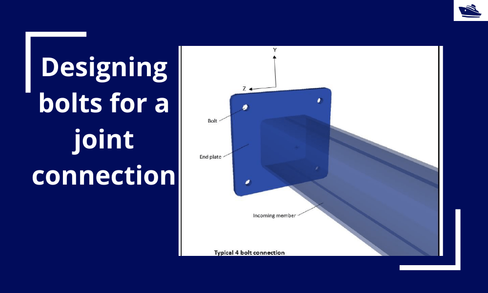
Designing bolts for a joint connection
Introduction Bolts are very commonly used fastening items and used in a variety of configurations. In this article, we will explore in-depth the design of a bolt used in connecting two members at a joint (bolted joint). We'll see what properties of the bolt are...
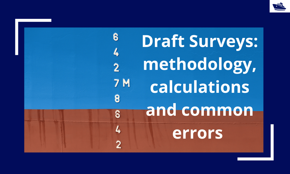
Draft Surveys: Methodology, Calculations, and common errors
Introduction Marine transport is the backbone of the global trade and reasonably can be considered to be the artery of the global manufacturing supply chain, as more than four fifths of the world merchandise trade by volume is carried by sea. Undoubtfully, the...
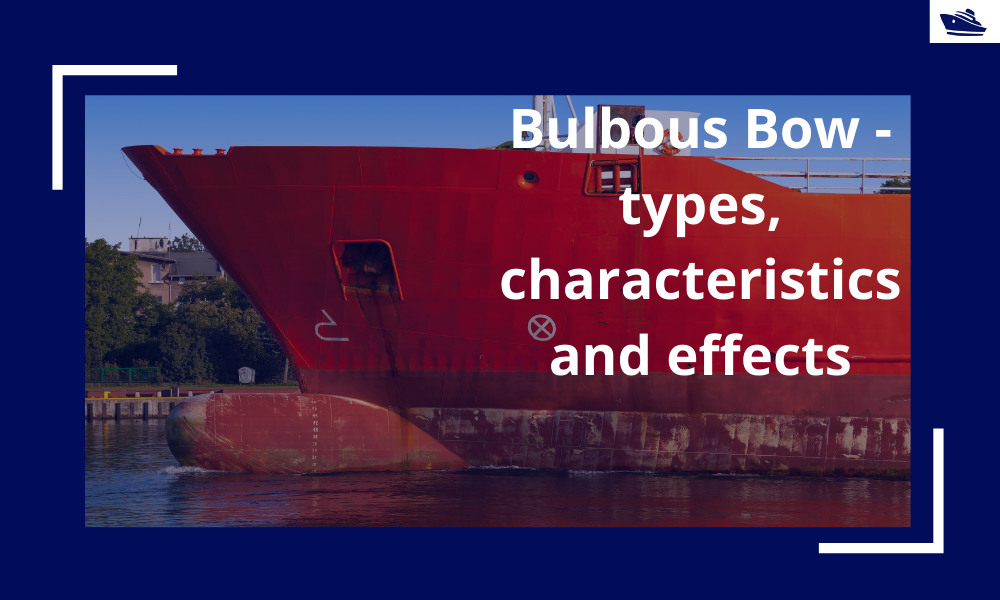
The Bulbous Bow – types, characteristics, and effects
This is Part 2 of the two-part series on Bulbous Bows. For Part 1, click here By Tamal Mukherjee, *This article originally appeared in May 2019 edition of Marine Engineers Review (India), the Journal of Institute of Marine Engineers India. It is being...
Using Class Rules to assess the Longitudinal Strength requirement of Barges
Introduction The longitudinal strength of a vessel is integral to its evaluation for a given purpose. To get an introduction to the topic, please refer to our other article https://thenavalarch.com/longitudinal-strength-ships-introduction/ In this article, we’ll see...
The why and how of freeboard calculation of a ship
Introduction Freeboard is a common term used in vessel operations. Freeboard is the smallest vertical distance between the waterline and the freeboard deck (generally the upper deck) along the length of the vessel. The term ‘smallest’ is of significance, as the height...
Thank you very much
for calculation
Thank you
I want to learn how to calculate the trim
Hi Jemil
Please go through any basic naval architecture book and you’ll learn. All the best!
Do you have a simple way I can calculate my trim and draft for my vessel
wrong interpolation formula, it should be:
T = T1 + (D – D1)*[(T2 – T1)/(D2 – D1)]