How to use empirical formulas to estimate the resistance of a Ship
Resistance estimation holds immense importance in the design stage of a vessel. Based on the results of the resistance estimation of a vessel, the selection of the right propulsion system is done.
There are three methods which are commonly used for ship resistance estimation
- Empirical methods – depending on the type and shape of the vessel, empirical methods like Holtrop-Mennen can be deployed for ship-shaped vessels. For planing and semi-planing craft, similarly, there is a multitude of methods like Mercier Savitsky, Fung etc. These methods are based on years of model testing data which are plotted in forms of charts/curves to provide resistance coefficients. The calculation of resistance follows the simple physical formulation of Force = Pressure x Area. However, these methods don’t provide a highly accurate or customized result and are mostly used only in early design stages.
- CFD Analyses – CFD analysis is a way to get much more customized and ‘closer to reality’ assessment of a ship’s resistance. This involves creating a complete 3D model of the vessel in a software which can perform fluid simulations and calculate the hydrodynamic forces on its body. However, CFD analyses can be performed only once the hull modeling (linesplan) of the vessel has been finalized. Also, CFD analyses are time consuming and may prove costly in preliminary design stages too.
- Model testing – the most accurate and reliable method for calculating a ship’s resistance is by performing a model test. It involves building a scaled down model of the actual vessel, performing tests on it in a model basin, and extrapolating the results to the actual vessel. However, model tests are usually performed at the end of the design cycle, and they are quite cost-prohibitive.
In the early design stages, with limited data available, empirical methods can be used to give a fair estimate of a ship’s resistance.
The Holtrop-Mennen method
In this article, we will discuss in detail an empirical method called the Holtrop-Mennen method, which is commonly used for ship-shaped vessels. This method was developed after performing regression analyses of random model experiments and full-scale data. The first publication of the method was in 1978 (See Ref 1), and it was further refined in 1982 to include some unconventional combinations of the main parameters of the vessel.
The method is limited to conventional ship-shaped vessels and is not to be applied for planning/semi-planing or high-speed crafts.
Components of a ship’s resistance and their estimation
The total resistance of the ship is subdivided into many components (see Ref 2):
- Frictional Resistance of the ship (RF) – this is the resistance which the ship’s hull’s surface encounters as a result of moving against water.
- Appendage resistance (RAPP) – this is the resistance which is experienced by the appendages on the ship – bilge keels, rudder, shafts, shaft brackets, struts etc.
- Wave-making resistance (RW) – this is the resistance which the ship encounters as a result of making waves on the free surface as it moves
- Bulbous-bow resistance (RB) – if the ship has a bulbous bow, it contributes to additional resistance near the water surface where the bulb emerges out of water
- Additional resistance of transom stern (RTR) – if the ship has a transom stern, it leads to additional pressure resistance due to an immersed transom
- Model-ship correlation resistance (RA) – this is an additional factor which is introduced to take into account for hull roughness.
We’ll now take them up one-by-one and describe the empirical methods for each.
Frictional Resistance of the ship’s hull (RF)
The frictional resistance of the ship’s hull is calculated from the basic formula for resistance which the ship’s hull surface experiences by moving against a viscous fluid (water):
Resistance = Resistance Coefficient x pressure x Surface Area
Pressure = ½ ρV2
Surface area = wetted surface area of the vessel.
The resistance coefficient is a function of the speed of the fluid and its viscosity. It is derived from the ITTC 1957 formula
Here, Rn is the Reynolds’ number of the fluid, which is calculated according to the formula below:
Rn = VL/ν
Where, V = relative speed of the vessel against water (includes current speed)
L = Length of vessel on waterline
ν = Viscosity of Water
The above formula for CF was adopted by the International Towing Tank Conference (ITTC) in 1957 at Madrid.
However, the frictional resistance coefficient was based on two-dimensional flat resistance theory, and didn’t take into account the three-dimensional form of the vessel. To account for this, a new factor called ‘form-factor’, k1, was introduced. Thus, the total frictional resistance of the vessel is
Frictional Resistance = RF x (1 + k1)
where RF = 1/2 ρwaterSV2 X CF
S = wetted surface area of hull
V = relative speed of water vs the hull
CF = Resistance coefficient as per ITTC 1957 formula
As per Holtrop-Mennen formulation, the form factor ‘k1’ is obtained from the formula below:
This involves calculations of multiple parameters like prismatic coefficient, length of run, and coefficient for stern shape which can be obtained from the geometric particulars of the vessel in question.
The wetted area of the hull can be calculated from the empirical formula below:
Appendage Resistance (RAPP)
The vessel may have multiple appendages to the hull. These may include – Rudder, Shafts, Shaft brackets, skeg, strut bossings, hull bossings, stabilizer fins, bilge keels etc. In a similar manner to the hull resistance, the resistance of the appendages of the vessel can be found out from a similar formula
Appendage Resistance RAPP = 1/2 ρwater(ΣSAPP) V2 x (1 + k2)eq x CF
The term 1/2 ρwater(ΣSAPP) V2 is the pressure on the entire surface area of all appendages. ΣSAPP = Total Wetted Surface Area of all Appendages. V = Vessel Fwd Speed (including current speed). ρwater = Density of Water
CF = Resistance Coefficient as per ITTC 1957 (CF = 0.075 / [log10 R)-2]2 where R = Reynolds Number (R = VL/ν), ν = Viscosity of Water, L = Waterline Length
The factor (1 + k2)eq is the appendage resistance factor (similar to the hull’s form factor) and is an area-weighted average of the factors for different appendages.
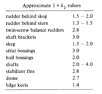
(1 + k2)eq = Σ{(1 + k2) SAPP}/(ΣSAPP), where (1 + k2) value for different appendages are taken from Table below
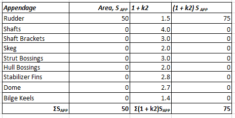
A simple table for calculating (1 + k2)eq can be created as below:
Wave making Resistance (RW)
When a completely submerged body moves in a non-viscous fluid, then the net force on the body (due to pressure normal to the surface of the body) is zero. This is because the pressures on the aft and forward halves cancel each other.
However, when the body moves with part of it above water, it creates waves which alter the pressure distribution around the hull and cause a net fore-and-aft force (see Ref [2]). This is called the wave making resistance, i.e., the force expended by the ship to maintain the wave system it creates at the free surface.
It is to be noted that this is NOT the resistance due the waves which are present in the sea. It is the resistance due to the waves created BY the ship when moving in calm water. The resistance created by external waves is called the ‘Added Wave Resistance’
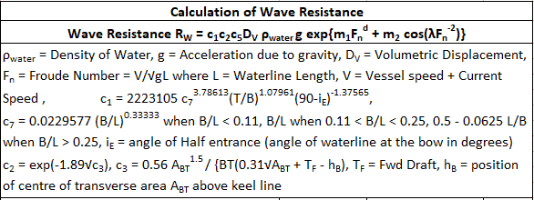
In the Holtrop-Mennen method for resistance estimation, the following formulae are used for calculation of Wave Resistance:
We can see above that the presence of a bulb (ABT is the bulb transverse area) leads to a reduction in the wave resistance by leading to a lower value of factor c2.
Additional pressure resistance of the Bulbous Bow (RB)
This is an additional resistance component due to the emergence of the bow above the water surface.
In the Holtrop-Mennen method, it is calculated using the following empirical formula:
We can see that the formula depends on the emergence of the bow above water (calculated from draft, height of bow and transverse area of bow).
Additional pressure resistance of due to transom immersion (RTR)
Similar to the bow emergence leading to additional resistance, a vessel with Transom stern also experiences additional pressure resistance when the transom immerses in water.
The below empirical relation is used in Holtrop-Mennen method to calculate this component of resistance. We can see that the formula depends on the area of the immersed transom.
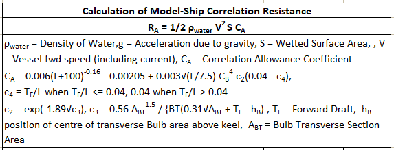
Model-ship correlation resistance (RA)
The model-ship correlation resistance is added to account for the effect of hull roughness, which in turn, is attributed to a number of factors:
- Structural roughness – caused due to the method used in fabrication of the hull (welded/riveted), or due to the waviness of plates etc
- Paint roughness – due to paints of rough texture, or bad method of application
- Corrosion resistance – caused by corrosion of external shell plating
- Marine fouling of the hull
To account for the above, a correlation allowance is introduced, which is given by the formulation as below (in Holtrop-Mennen):
That brings us to the end of this discussion on using Holtrop-Mennen method for prediction of resistance of ship-shaped vessels. Please note that this method should be used only in early design phases, and is not to be relied upon for accuracy. For more firm predictions, it is recommended that a full-fledged resistance estimation be performed using a CFD analysis or a model test.
References
- An approximate power prediction method, Holtrop Mennen, 1982
- Principles of Naval Architecture, Edward V. Lewis, Vol II
- ITTC document – https://www.ittc.info/media/8185/75-04-05-01.pdf
- ITTC document – https://ittc.info/media/2065/75-02-05-01.pdf
- https://en.wikipedia.org/wiki/Reynolds_number
- https://www.cambridge.org/core/books/ship-resistance-and-propulsion/modelship-correlation/F34DC26DAFDBA076213C9D5F67F6A762
TheNavalArch has developed its own calculator for estimating the resistance of a ship as per Holtrop-Mennen method. Please do take a moment to look at it below.
Disclaimer: This post is not meant to be an authoritative writing on the topic presented. thenavalarch bears no responsibility for the accuracy of this article, or for any incidents/losses arising due to the use of the information in this article in any operation. It is recommended to seek professional advice before executing any activity which draws on information mentioned in this post. All the figures, drawings and pictures are property of thenavalarch except where indicated, and may not be copied or distributed without permission.

Using MS Excel to evaluate the Stability of existing Barges
Barges are the simplest, and yet most widely used of marine vehicles. They are used for a variety...
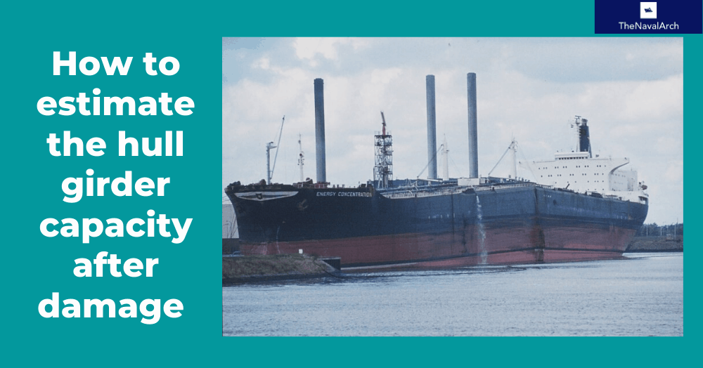
The importance of ULS (Ultimate Longitudinal Strength) and how to assess it for a damaged hull
by Alessandro La Ferlita, Naval Architect Ultimate hull girder strength represents the maximum...
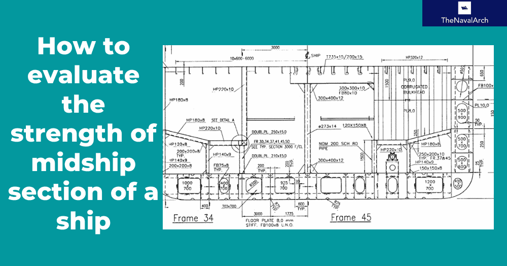
How to calculate the strength of Midship Section of a Ship
The mid-ship section of a ship is a defining structural drawing of the vessel. It represents the...
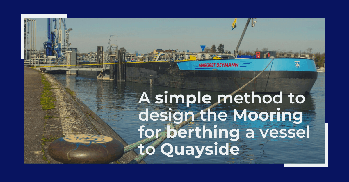
Designing the berth mooring of your vessel with this simple yet effective method
A vessel at berth experiences much lower forces compared to a vessel in the open sea due to the...

Bulbous Bows – History and Design
by Bijit Sarkar, Naval Architect Introduction The eternal search of a naval architect – a perfect...
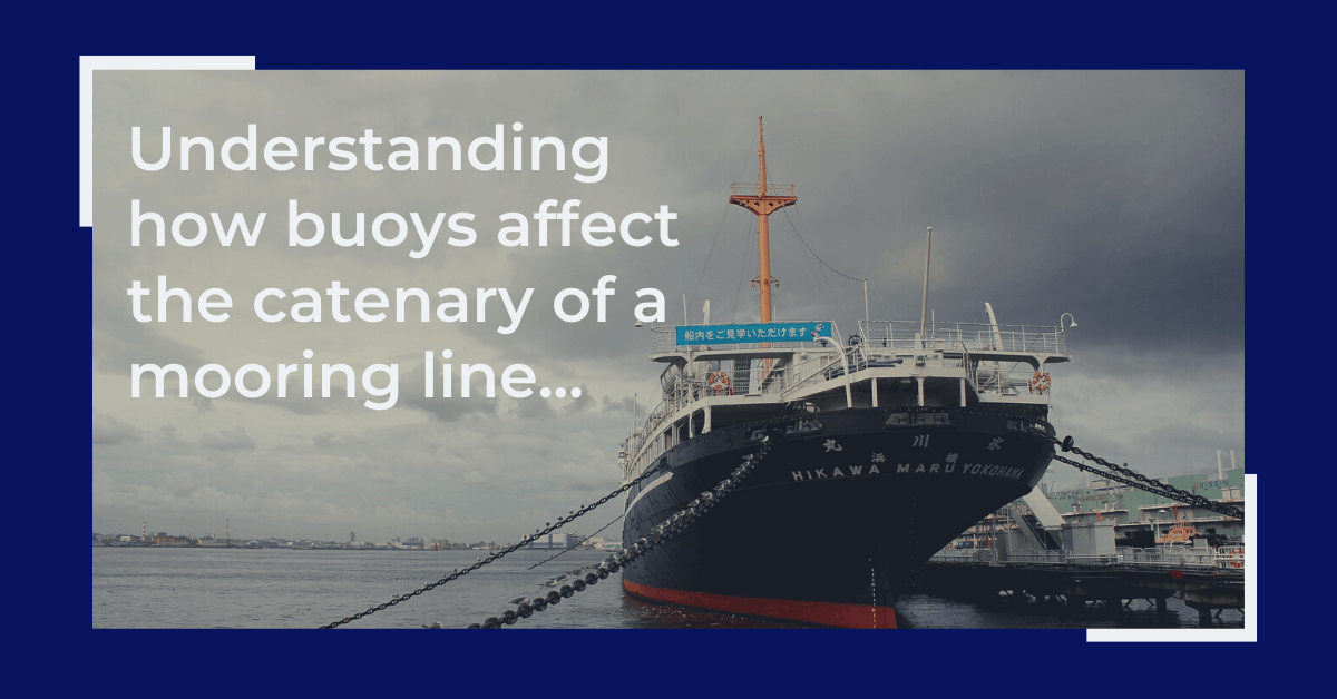
Understanding how buoys affect the catenary of a mooring line
What is a mooring line? Mooring lines generally comprise ropes, wires, chains or combination of...
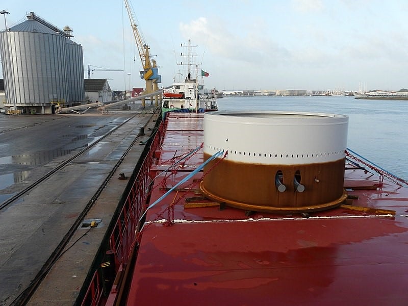
Calculating forces on a ship’s deck cargo – a simplified approach
A cylindrical deck cargo (Source: Wikimedia) Introduction A ship’s deck is used to transport many...
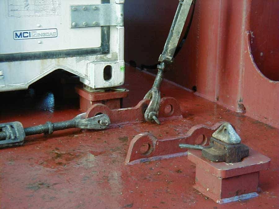
Designing a pad-eye: little items with big intricacies
Pad-eyes are one of the smallest and most universally used structural items in the maritime and...
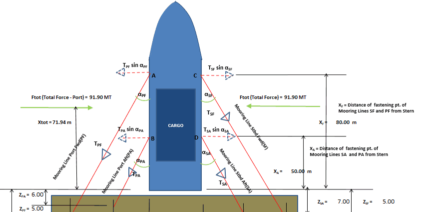
Vessel with Stern on Quay: A simplified method for mooring design
A vessel at berth experiences much lower forces compared to a vessel in the open sea due to the...
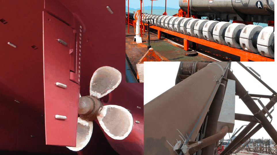
Cathodic Protection – Ships, Offshore Platforms, FPSO’s and Pipelines: a comparison
Cathodic protection of a structure is an exercise which requires close study of the structure on...





I think CFD calculations become more and more Important. It is much more precise in comparison with empirical calculations and not so expensive as towing tank.
First that for sharing this article, it is simple and easy to understand and apply. regarding the use of the CFD (comment1), it is important for a NavArch to understand the principals calculation and steps, and use them appropriately yo check the CFD results. Remember, the CFD is treated as a black box. so setup the model (input) and get your output. A good NavArch can always manually check the calculation (simulation result), there is a need to now when the result is good or acceptable….
Hello,
For the Wave making Resistance (RW), in the case IE (half angle of entrance) is 90deg it will make C1 is 1/0.
How to avoid that condition? Please note the Cwp is 1.0
Hi Nafuat
Thanks for the comment. I don’t think Holtrop-Mennen can be used for a half angle of entrance of 90 deg which is for a flat plate. It is applicable for a ship-shaped vessel which has a streamlined shape and half-angle-of-entrance is less than 90.
If you need specific help, please write to info@thenavalarch.com with more details and we can help.
Regards