Introduction
Stanchions – a familiar term for mariners and ship designers. What are Stanchions?
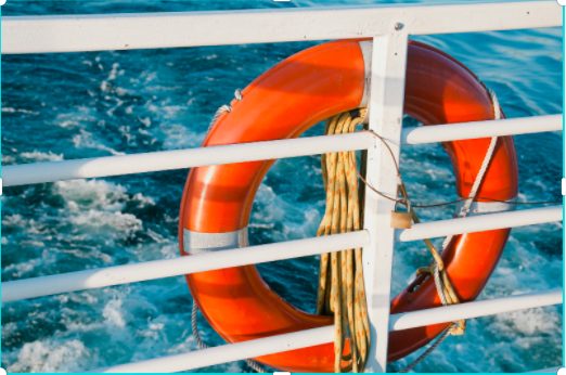
A stanchion is generally a vertical pipe or beam which is used to support some structural item or provide support rails on the deck. In ships, the most common type of stanchion is support rails at the edge of the deck for people onboard to lean on to prevent falling over. It can also be used to support lifesaving appliances like lifebuoys/liferafts etc, and many times reinforced to support heavier structures.
Stanchions for hand rails
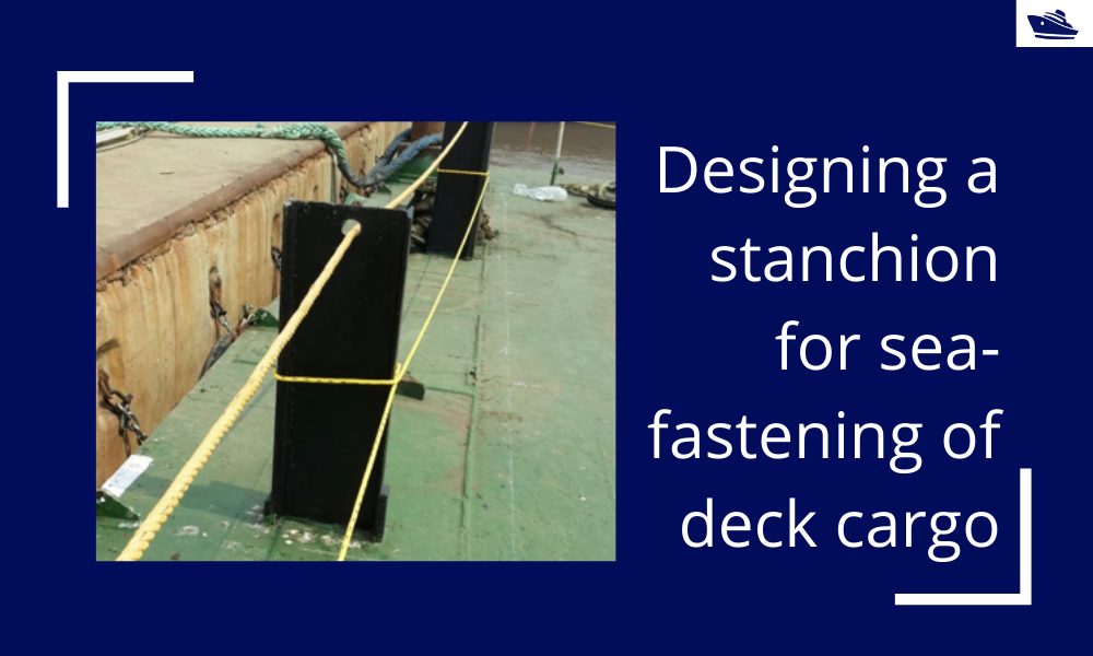
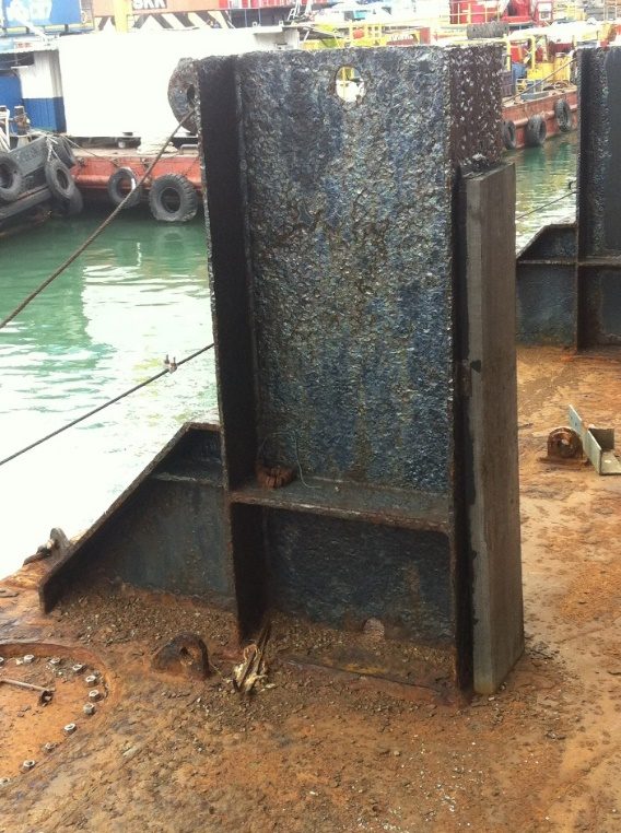
Stanchion/Stopper for seafastening
For seafastening of cargo, the stanchion needs to be designed to take the loads on the cargo during seafastening. Basically, the stanchion/stopper is placed at the sides and ends of the cargo to prevent the cargo’s sliding in the transverse and longitudinal directions respectively. This can be seen in the figure below:
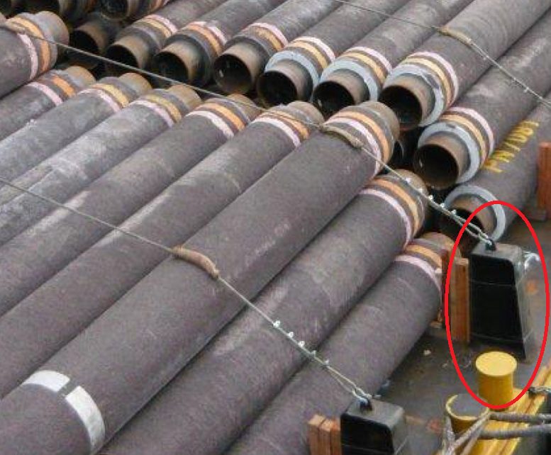
Stanchion used to support pipes on deck
Interchangeably, these stanchions are also called stoppers. However, the stopper is a more generic term and is used to cover other geometries too. For a comprehensive article on stoppers, please check out this article on stoppers.
The most common stanchion used is the H-beam stanchion due to its simplicity. Pipe stanchions may also be used in some cases.
In this article, we will look into the design of an H-beam) stanchion and the various stresses that govern its strength.
These principles can be used to assess existing stanchions on the deck of a vessel for their suitability for use with a given cargo too.
A simple H-beam stanchion drawing is shown below:
In some cases, such a stanchion may be further reinforced at on one side to take greater loads, as shown below:
Stanchion with reinforcement at back face
Loads
The cargo load on the stanchion can be of two types:
- A point load – the stanchion can take a point load if the cargo if fastened to the stanchion using a lashing. In this case, the stanchion generally has an in-built lashing eye, or an external pad-eye can be welded to it (generally at the top) to create the fastening point.
- Distributed load – a stanchion takes distributed load when the cargo is resting against it, and full or partial face of the stanchion takes the load.

Stanchion with Distributed Load
Stanchion with point load at the top
Stress Check
In this section, we’ll see for the two cases of loading, the applicable stresses, and how to go about calculating them.
Case 1 – Distributed Load
When the cargo is resting against the face of the stanchion, the total load and stresses on the stanchion can be calculated by the following method:
- Calculate the transverse/longitudinal force on the cargo. The transverse/longitudinal force on the cargo can be calculated using an analysis, or using empirical relations (check out our product Cargo Forces and Accelerations)
- Divide the total transverse or longitudinal force by the number of stanchions in the respective direction. For example, if the total transverse force on the cargo is 100 MT and there are 4 stanchions supporting it, the load on one stanchion in 25 MT
- Calculate the design load per unit length by dividing the load on the stanchion by the total height of the stanchion which takes the distributed load. It is to be noted that not the entire face of the stanchion may take the load, and only the part which takes the load should be taken into account for calculations.
- Calculate the design moment on the stanchion due to the distributed load
- Calculate the section properties of the H-beam section of the stanchion. This includes shear/tensile areas and section moduli about the two axes.
- The stanchion is not subject to axial stress due to no load being in the axial direction.
- The shear stress is calculated by dividing the total transverse/longitudinal load by the shear area
- The bending stress is calculated by dividing the total transverse/longitudinal moment by its respective section modulus.
- Weld Check – it is important to perform strength check for the weld that secures the stanchion to the deck. Similar to the stanchion, shear and bending moment checks need to be performed for the weld too by calculating its shear area and section moduli.
Case 2 – Point Load
When the load on the stanchion is a point load, the steps of calculation still remain the same as for the distributed load, except for the following changes:
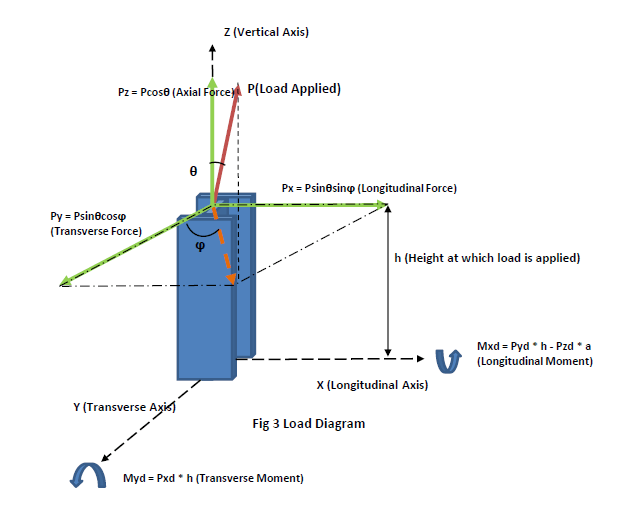
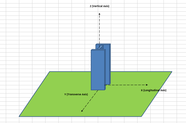
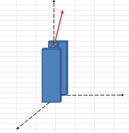
Stanchion with point load – force resolution
- The load on an individual stanchion is the load on the lashing between cargo and the stanchion. This load comes from seafastening calculation
- The load on the stanchion will resolve to loads along the three axes of the stanchion as shown below
These loads will also lead to design moments about both X and Y axes as shown above.
- The stanchion will experience a tensile force as well due to the axial component of the design load
- Out-of-plane bending stresses also need to be checked (for moment about Y-axis)
- A local web-yield check may also need to be performed for stanchions using AISC formula k1-3
Thus, depending on the type of loading, the stress checks for a stanchion vary. If the stanchion is found to fail in these checks, either a full-fledged FE Analysis may be carried out to further ascertain the suitability of the stanchion, or some strengthening of the stanchion may be recommended.
That brings us to the end of this article on stanchions. Assessing the suitability of an existing stanchion, or designing new ones for a seafastening operation require us to look into every strength aspect of the stanchion in detail.
Please do take some time to explore TheNavalArch’s product for stanchion design.
Disclaimer: This post is not meant to be authoritative writing on the topic presented. thenavalarch bears no responsibility for the accuracy of this article, or for any incidents/losses arising due to the use of the information in this article in any operation. It is recommended to seek professional advice before executing any activity which draws on information mentioned in this post. All the figures, drawings, and pictures are property of thenavalarch except where indicated, and may not be copied or distributed without permission.
https://thenavalarch.com/software/maritime-industry-thenavalarch/marine-operations/sefastening-design/mt-8-dog-plate-design-spreadsheet/
https://thenavalarch.com/software/maritime-industry-thenavalarch/marine-operations/marine-transportation/mt-3-cargo-forces-accelerations/
https://thenavalarch.com/software/maritime-industry-thenavalarch/marine-operations/sefastening-design/mt-7-stopper-design-spreadsheet/
Marine Propeller Shafting and Shafting Alignment – Part 1
*****This article first appeared in July 2018 edition of Marine Engineers' Review (MER), India. We're reproducing it for the readers of our blog***** Abstract: Since 2013, Shaft Alignment Practice has undergone a change, with developments of Analysis tools. At the...
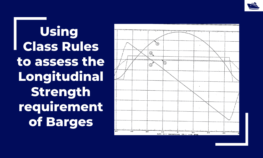
Using Class Rules to assess the Longitudinal Strength requirement of Barges
Introduction The longitudinal strength of a vessel is integral to its evaluation for a given purpose. To get an introduction to the topic, please refer to our other article https://thenavalarch.com/longitudinal-strength-ships-introduction/ In this article, we’ll see...
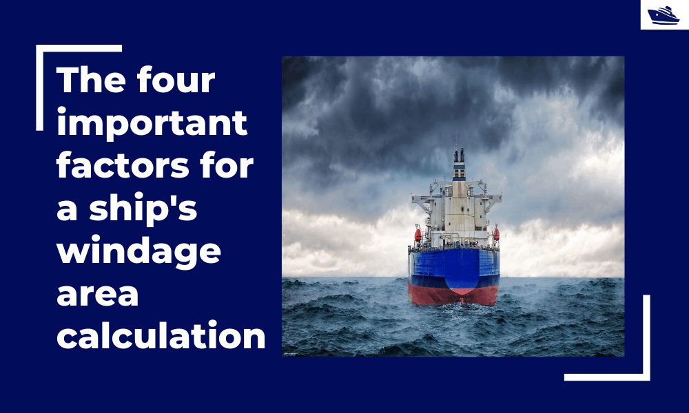
The four important factors for a ship’s windage area calculations
Introduction The windage area of a vessel or offshore structure is the area that is exposed directly to the wind. As is obvious, this is the area of all items above the waterline. This will include Part of the hull/offshore structure above the waterline...
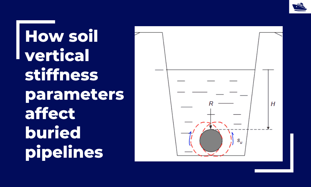
How soil vertical stiffness parameters affect buried pipelines
Introduction Pipe soil interaction is a critical subject of analysis in the field of the offshore industry. A pipe once buried in the seabed is usually in equilibrium with the surrounding soil. There are however various forces which are still in action even if the...
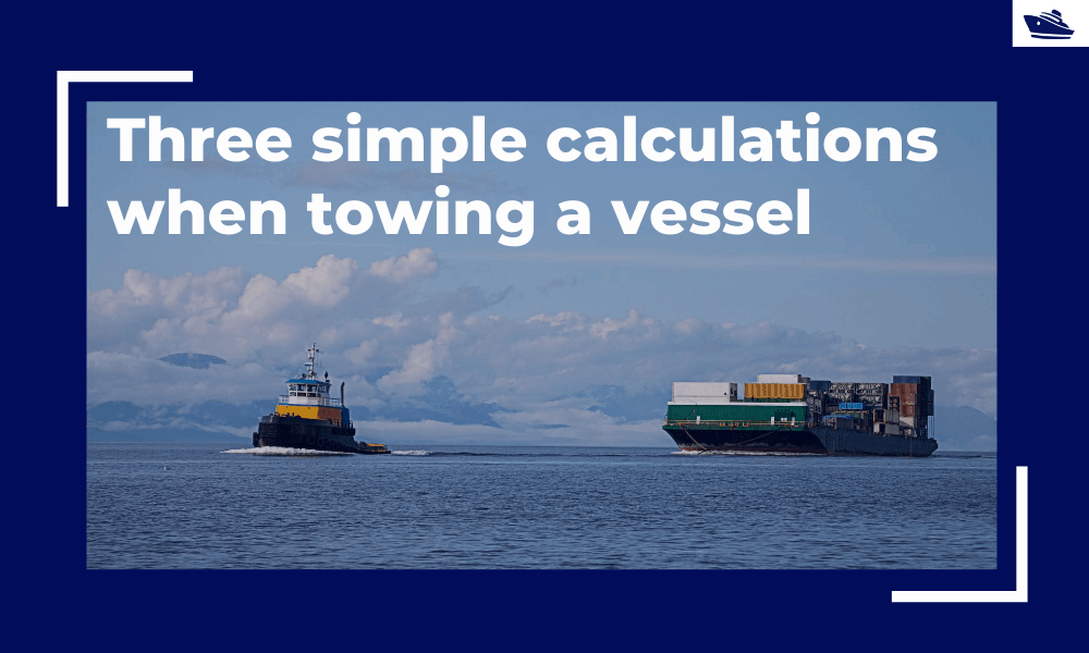
Three simple but useful calculations when towing a Vessel
In this article, we will explore three simple but useful calculations that can be used for towing operations. They are: Towline Stiffness Propeller race Towing bridle force DNV-RP-H1o3, Modelling and Analysis of Marine Operations, FEBRUARY 2014 has been referenced...
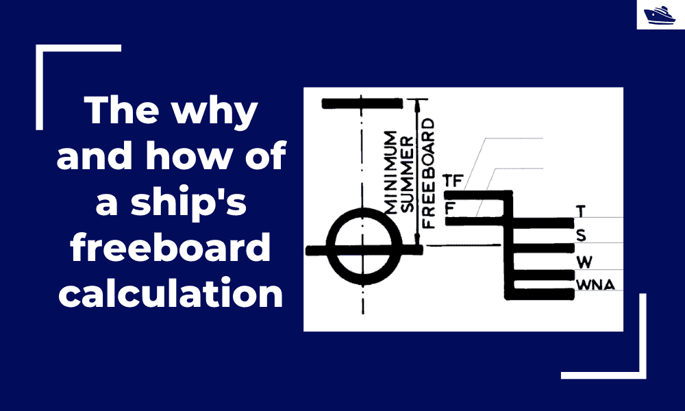
The why and how of freeboard calculation of a ship
Introduction Freeboard is a common term used in vessel operations. Freeboard is the smallest vertical distance between the waterline and the freeboard deck (generally the upper deck) along the length of the vessel. The term ‘smallest’ is of significance, as the height...
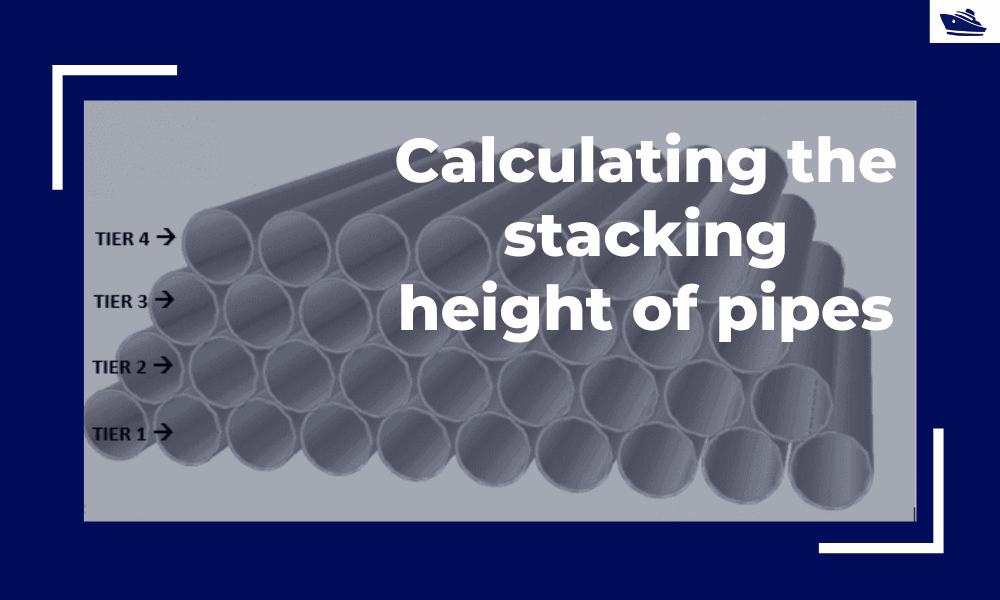
Calculating the maximum stacking height of pipes
Introduction Pipes (or linepipes or joints) are used for multiple purposes and locations in the maritime/offshore industry. Onshore and offshore pipelines are used for transportation of fluids on land, over and underwater. Pipes are fabricated in an onshore facility...
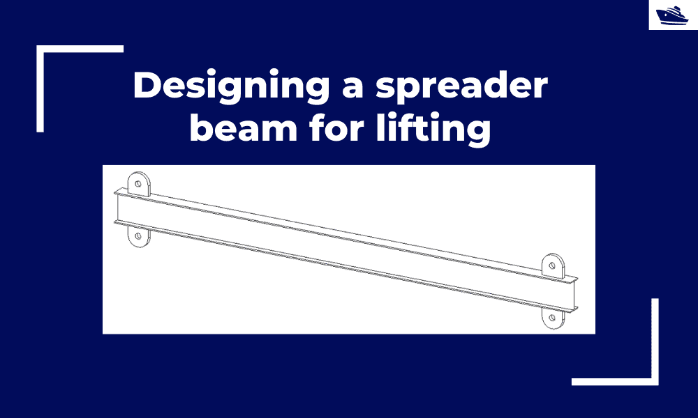
Designing a spreader beam for lifting
Spreader beams are universally applied gear which is widely used in various types of lifting operations, onshore and offshore. In this article, we will explore the design of a basic spreader beam and see what design checks are needed to establish the suitability of a...
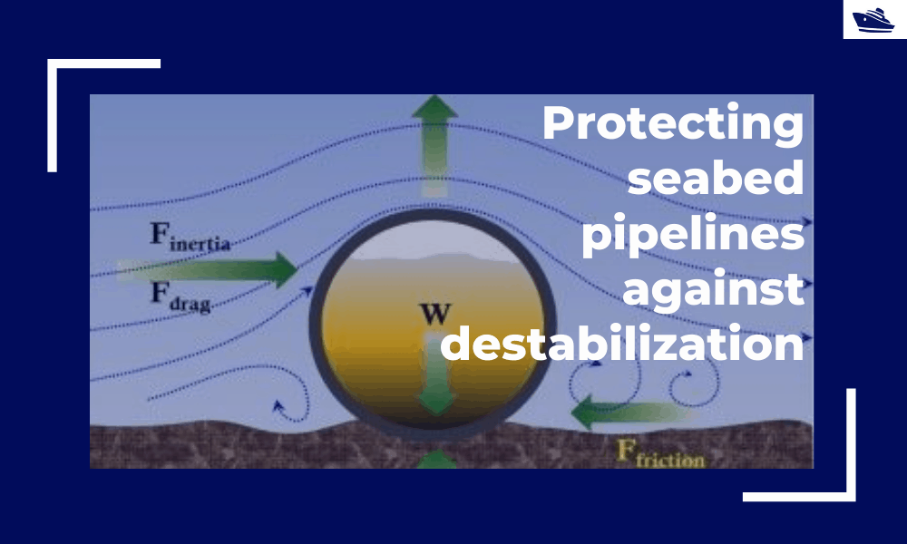
Protecting the seabed pipelines against destabilization: Identifying and qualifying the risk
The Philosophy Cable hydrodynamic stability is one of the most fundamental design topics which are addressed by cable installation engineers. In its simplest form, a simple force balance approach may be considered to ensure that the cable is not displacing...
Safe Towing: Calculating a towline’s catenary and sag
Introduction Towlines connect a tug to the vessel being towed and are defined by multiple characteristics like Weight, Diameter, and Stiffness. The tension in the towline during the towing operation is not static but keeps varying with the distance between the tug and...

Grazie. Tutto molto interessante
hello thanks you