Introduction
Pipe soil interaction is a critical subject of analysis in the field of the offshore industry. A pipe once buried in the seabed is usually in equilibrium with the surrounding soil. There are however various forces which are still in action even if the pipe is buried :
- Gravitational forces of the soil
- Pipe’s own hog and sag due to end constraints
- Seismic forces
- Soil displacement and liquefaction
- Accidental dropping of an anchor or a heavy point load
- Trawl forces
- Pipe’s thermal expansion and contraction
- The pressure of its content
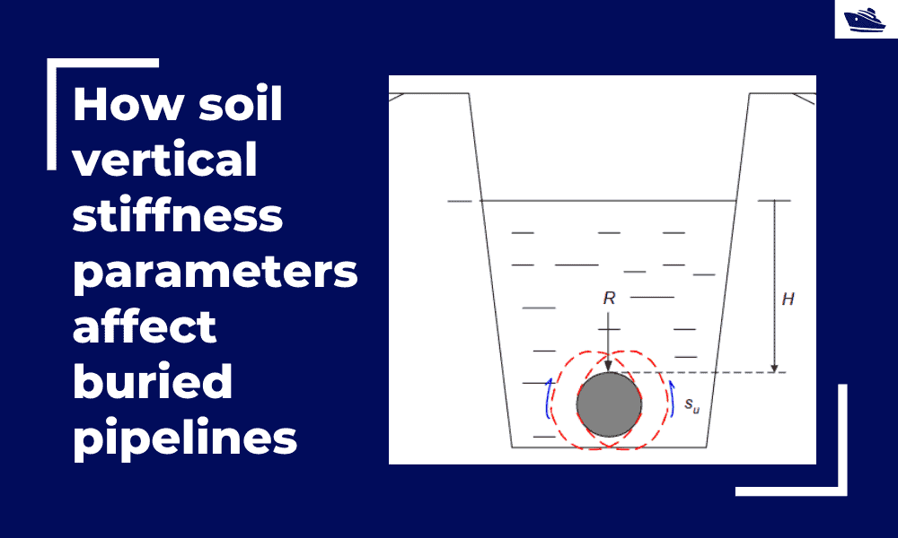
The soil layers on the top resist the pipeline uplift and bottom soil layers prevent further downward movement of the pipeline. The resistance over the pipe vertical movement has been a subject of deep research in the industry. Evaluation of force springs are relevant for the calculation of:
- Uplifting force during partial or complete recovery of a buried pipeline or cable, without compromising the flexible product criteria.
- The uplifting force required during removal of a decommissioned cable
- Forces on a buried pipeline during self-upheaval
- Evaluating the strength of end fixity during free-span assessments.
etc.
The lateral forces on the pipeline shall be discussed in a separate article.
Several papers have been written over this topic. The DNV Guideline DNV-RP-F110 “Global buckling of submarine pipelines – Appendix B – Soil resistance for buried pipeline’ is the result of various JIPs, papers, and lab-based research which gives recommendations regarding the uplift and downward resistance modeling for buried pipelines. The resistance models in this guideline are developed using 2D analysis where the length of the pipe has no influence. This is particularly useful for 3D tools like OrcaFlex and OFFPIPE, where the 2D force-displacement evaluation may be applied as a distributed load over the requisite length for the given penetration. Hence, the guideline helps us evaluate the vertical force-displacement curve or ‘spring curve’ for the buried pipe. For beam analysis, the simplification of soil in the form of distributed vertical spring is an accepted methodology in the industry.
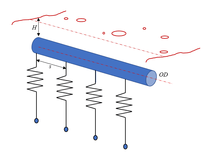
Figure 1:Conceptual representation of force springs on the buried pipeline
Factors influencing vertical force on the pipe
What are the factors which influence the vertical force on the pipe?
The force-displacement relationship is typically represented as a poly-linear spring where the slopes and magnitudes at various displacements. When the pipe displaces, there is a short-term elastic force development
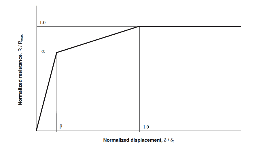
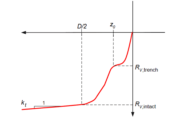
Figure 2: Typical uplift and downward force-displacement curves
The factors determining the type of curve are based on:
- Soil type:
- History of soil disturbance: Particularly for the undrained soil types, the strength of the soil is dependent on the type of trenching method used, and the level of backfill into the trench.
- Pipe dimensions
- Pipe movement direction: Uplift or downward resistance
- The depth to which the pipe is buried
- Soil Failure model: Global or local
Three of the above factors are discussed below:
Soil type:
The nature of force-displacement curves is completely different when the soil in which the clay is buried is “predominantly” based on a cohesive (clay) and cohesionless (sand and rock) soil type. “Predominantly” because soil, especially backfilled material is never a 100% uniform material. The information is made from the study and judgment of the CPT and survey data from the site. Note that during the uplift of the pipe in predominantly cohesionless soil it is usually against a backfill material of loose sand, while it can be considerably unpredictable for cohesive soil. A conservative approach may be used under a complete lack of data or estimation.
History of soil disturbance:
The pipe is usually buried below the seabed level by various trenching techniques. The type of trencher used is dependent on the prevailing site conditions as well as resources and contractual requirements. While jetting is recommended for the softer clay or sand, stiffer clay would need plowing. Both trenching techniques have different backfill situations. Particularly for the undrained seabed, how the soil ‘consolidates’ overtime also determines the soil stiffness above the pipeline. Thus, it is important to know how and when the trenching was performed in order to assess the soil stiffness. Slowly over time, the soil moves towards an Intact structure (in other words, remotely disturbed). The more the soil moves towards an intact condition, the bearing capacity of the soil increases.
Soil failure models
When the pipe underneath the seabed displaces, it applies force to the soil in the vicinity. The soil can sustain some pressure beyond which the soil loses its stability and undergoes failure. Failure can be in two ways:
- Global failure
- Local failure
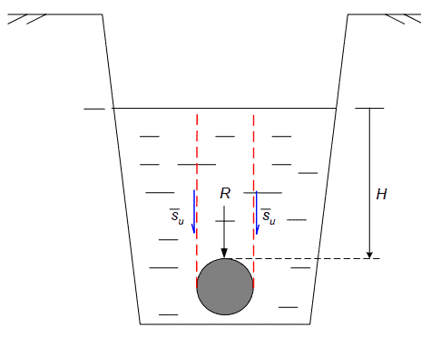
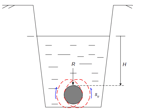
Figure 3: Global and local soil failure scenarios
While global failure represents an entire column of soil above the pipeline which can fail (i.e. loose bond with adjoining soil wall), local failure can be due to limited soil movement around the pipe, where a layer on to of pipe flows down below the pipe. Local failure is usually applicable for small movements or pipe’s uplifting due to residual bending or pipe expansions which disturbs only the local soil layer around the pipe. When the pipe is lifted up / recovered, the entire soil column above the pipe fails and global soil failure is applicable. Both approaches have a different force-displacement profile. If no failure situation is known, a conservative soil failure model and corresponding curve must be used.
TheNavalArch team understands the need for engineers to understand the impact of soil resistance on their projects and we’re developing a tool to generate appropriate soil spring along with the pipe beam elements. The outcome of the tool is a force-displacement curve which is to be copied onto a spring/ link element in any FEM tool. The force springs are applied at regular intervals of the pipe finite element. No additional soil loads are needed on the model. The tool being developed by TheNavalArch does not evaluate the pipe loads and stresses; it evaluates only soil resistance capacity. The resistance force generated by the tool should also not be confused with resistance force on vertical structures (piles) and should be applied only to horizontal pipes.
Disclaimer: This post is not meant to be authoritative writing on the topic presented. thenavalarch bears no responsibility for the accuracy of this article, or for any incidents/losses arising due to the use of the information in this article in any operation. It is recommended to seek professional advice before executing any activity which draws on information mentioned in this post. All the figures, drawings, and pictures are property of thenavalarch except where indicated, and may not be copied or distributed without permission.
-

DNV RP-F105 – Pipeline Free Span Analysis Tool (Full Version)
$149.00 Add To Cart -
J-tube cable pull-in load calculator
$99.00 Add To Cart -
Subsea Cable Installation Calculator
$39.00 Add To Cart -
Dropped Object Analysis Tool
$99.00 Add To Cart -
Pipeline On-bottom Stability Tool (DNV-RP-F109)
$99.00 Add To Cart -
Horizontal Pipe Soil Resistance – Vertical Spring Generator
$99.00 Add To Cart -
Drag Force Calculator for Subsea Pipeline
$49.00 Add To Cart -
Spoolpiece Lifting Design
$99.00 Add To Cart -
DNV RP-F105 – Pipeline Free Span Analysis Tool (Compact Version)
$79.00 Add To Cart
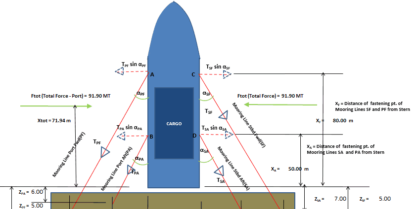
Vessel with Stern on Quay: A simplified method for mooring design
A vessel at berth experiences much lower forces compared to a vessel in the open sea due to the milder environment, but it still requires a mooring configuration suitable to the forces it experiences, and also suitable for the type of berthing configuration adopted....
Cathodic Protection – Ships, Offshore Platforms, FPSO’s and Pipelines: a comparison
Cathodic protection of a structure is an exercise which requires close study of the structure on which it is going to be implemented. The type and quantity of cathodic protection by anodes will depend upon multiple factors: the Geometry of the Structure, the...
Role of a naval architect – a walkthrough (Part – 1)
This is the first in a series of articles on 'Role of a Naval Architect' by Mr Bijit Sarkar, a Naval Architect with 35+ years of experience in ship design and shipbuilding. I would define a naval architect as one who has the ability to greet the client as he/she walks...
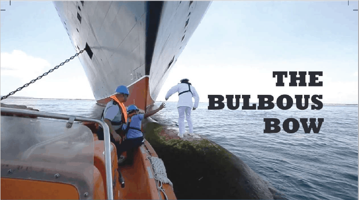
The bulbous bow – why some ships have it and others don’t
By Tamal Mukherjee, This is the Part 1 of a two part article on the Bulbous Bow. Part 2 can be accessed here *This article originally appeared in May 2019 edition of Marine Engineers Review (India), the Journal of Institute of Marine Engineers India. It is being...
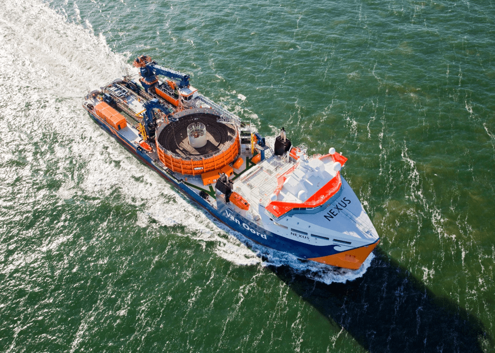
Mitigating risks during subsea cable installation
Over the last 20 years, the interest in offshore wind power generation has increased substantially. Offshore Wind Energy currently provides only 0.3% of world power generation, but the potential is really vast. In the next 20 years the offshore wind industry is set to...
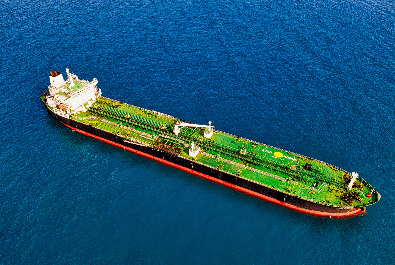
A simple method of selecting the right anchor for mooring a tanker/gas carrier
Anchoring is a fundamental and sensitive operation for a vessel. When a vessel is at anchor, it swings to align itself along the direction of the dominant environment. The anchor is supposed to hold the vessel in varying environmental conditions depending on where the...
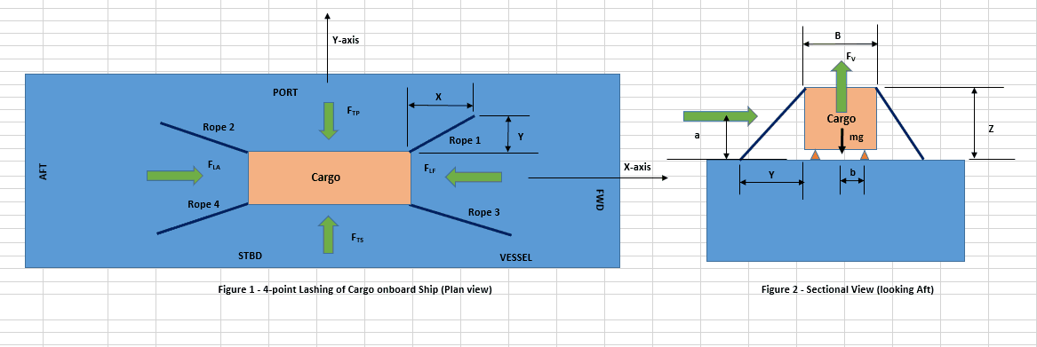
Designing a simple 4-point lashing system for a Deck Cargo
Introduction Lashing of a deck cargo on a ship involves different means and mechanisms to secure the cargo to the deck of the ship. This ‘securing’ is important to contain the movement of the cargo in view of the ship motions during the transportation. The simplest...
Calculating a Ship’s Design MBL using OCIMF MEG-4
In Part 1 of this article, we saw a step by step guide to calculate the Environmental forces on a vessel based on “Standard” environmental criteria defined in Section 3 of OCIMF Mooring Equipment Guidelines Fourth Edition (MEG-4) in order to determine the ship’s...
Selecting the right equipment for towing operations – Emergency Towing
In Part 1 of the article, we discussed the regular towing arrangements and how to select the towing gear for the same. In this part, we will discuss the components of the emergency towing arrangement and how to select them. The purpose of emergency towing equipment is...
Preliminary Rigging Arrangement Design OF 4 point, Single Hook Lifts for Non-Specialists
by Michael Harwood, PE, PMP Overview Lifting by crane is a basic construction operation that dates back to at least Sixth Century BC (ancient Greece for example) and the lifting operation itself dates back much further. It is a very common operation in present-day...

would like to have access