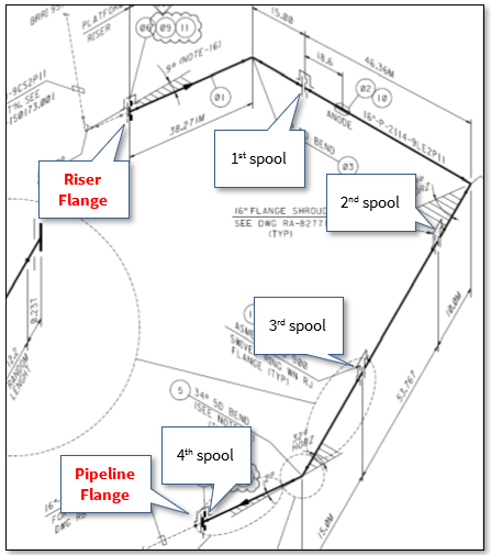
In the offshore construction industry, the connection between the newly installed pipeline and the riser is accomplished via a series of ‘spoolpieces’ (or spools). The spool is fabricated by welding pipe joints to form an L–shaped, Z–shaped, or possibly a straight pipe. The figure below shows that four spools connect the riser flange to the pipeline flange, where the first, second, and fourth spools are L-shaped, whereas the third one is a straight spool.
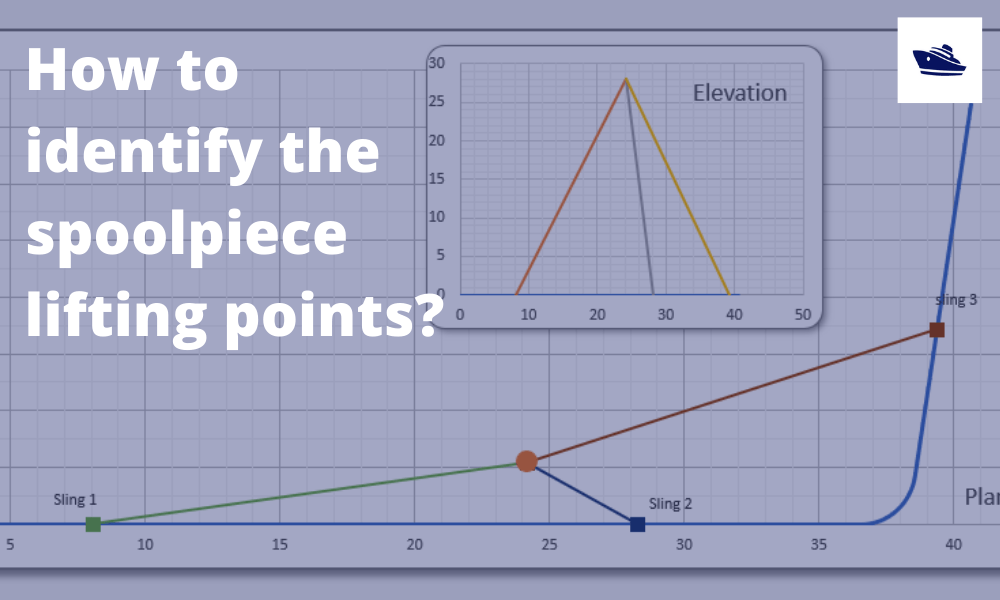
The lifting analysis of a subsea spoolpiece typically yields the specifications of the lifting slings and the lifting configuration, which represents the location of the pick-up (rigging) points. In addition, the analysis checks the stresses in the spools resulting from the lifting forces. However, the pipe stresses would be of concern in limited cases where we have to use a small lifting angle (with the horizontal), and the bend angle is approximately 90 degrees, coupled with a small pipe (e.g., 8 inches or less). Otherwise, lifting the spool does not usually cause stresses exceeding the allowable limits.
In all cases, we must obtain the lifting configuration; thus the tension in the wires, to correctly choose the suitable slings. That means we must find/purchase the slings matching the analysis results, which may cost much. However, the main problem is the potential delay of providing the slings if we have a tight schedule, e.g., when changing the lifting configuration of the closing tie-in spoolpiece.
What if the lengths of the available slings become an input in the analysis procedure? In other words, the question becomes, “where can I install a sling of a particular length on the spool, with a particular hook height?” So if we were able to change the way we do the analysis, we would be using slings available in the stock, provided they have reasonable sizes and lengths, saving costs in many ways. Is that possible?
The answer is yes. The basic idea of obtaining the location of the pick-up points is that they represent the intersection between a sphere and a straight line, but how?
The sphere is centered at the hooking point, and its radius is the sling length. That means that the sphere surface represents all the possible points in space around the hooking point that are at an equal distance of the sling length from it. These points, of course, include the pick-up points we are looking for; thus, our job now is to find the intersection points between the sphere and the spool straight lines. See the below illustrating sketch.
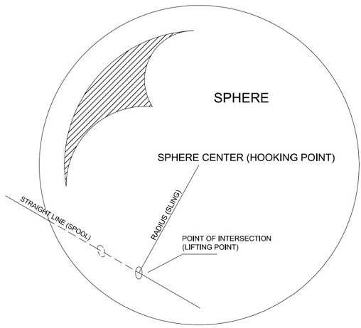
Mathematically speaking, the sphere equation is defined by the center (hooking point) and the radius (sling length). And of course, the hooking point should be at a suitable vertical distance (hooking height) from the center of gravity, which should be calculated as well. Of course, that hook height should be reasonably shorter than the shortest sling. On the other hand, the spool equation is identified by the spool pipes lengths and bends’ angles. Consequently, the two equations must be solved simultaneously, yielding, ideally, two quadratic the root(s), representing the coordinates of the pick-up points of one particular sling length on a specific spool pipe.
Furthermore, the tension in the slings can be found by simple equilibrium equations of rigid body mechanics. So we have six equilibrium equations: three for summing forces in the three coordinate directions and three for summing moments. In that case, if we imagine that the max number of slings is six (which is practically too many), we can use as many equations as the number of slings we wish to use. Ultimately, we solve these equations simultaneously, get the tension, and subsequently choose the proper slings or probably check if the tension matches the slings we have in stock.
This procedure can be done by Excel VBA. A program has been developed (link at the bottom of this article) that performs the whole process from identifying the center of gravity, getting the pick-up points, and obtaining the tension. And, of course, the user can redistribute the slings and get new tension values if he wishes. Obtaining positive tension values is a sign that the slings distribution is physically possible and stable.
The following video explains the concept graphically.

Mohamed Hermas
Founder, Offshore Engineering Guide
Mohamed is an Offshore Pipeline Engineer and a CAE specialist, holding an M.Sc. in Subsea Engineering from the University of Aberdeen. He has been working in the offshore construction industry, with a focus on pipelines and cables, for 19 years.
Hermas has served in several capacities over the course of his career. He began as a field engineer, then project engineer, installation engineer, and pipeline engineer in many places worldwide.
In 2016, Mohamed was awarded the Chartered Engineer title from the Institution of Mechanical Engineers. In the same year, he launched a website for offshore construction professionals, with the following address: offshoreengineerguide.com
Mohamed’s interest in studying the finite element method began in 2017. By 2018, he has built his first mathematical model for stress analysis by Matlab language. Subsequently, he developed solvers serving many engineering purposes using Matlab, Wolfram language, and Excel VBA. He helps companies and individuals to make tailored programs/calculators for different engineering applications for which there is no software package available in the market.
Disclaimer:
The views, information, or opinions expressed in this article are solely those of the author and do not necessarily represent those of TheNavalArch Pte Ltd and its employees
Marine Propeller Shafting and Shafting Alignment – Part 1
*****This article first appeared in July 2018 edition of Marine Engineers' Review (MER), India. We're reproducing it for the readers of our blog***** Abstract: Since 2013, Shaft Alignment Practice has undergone a change, with developments of Analysis tools. At the...
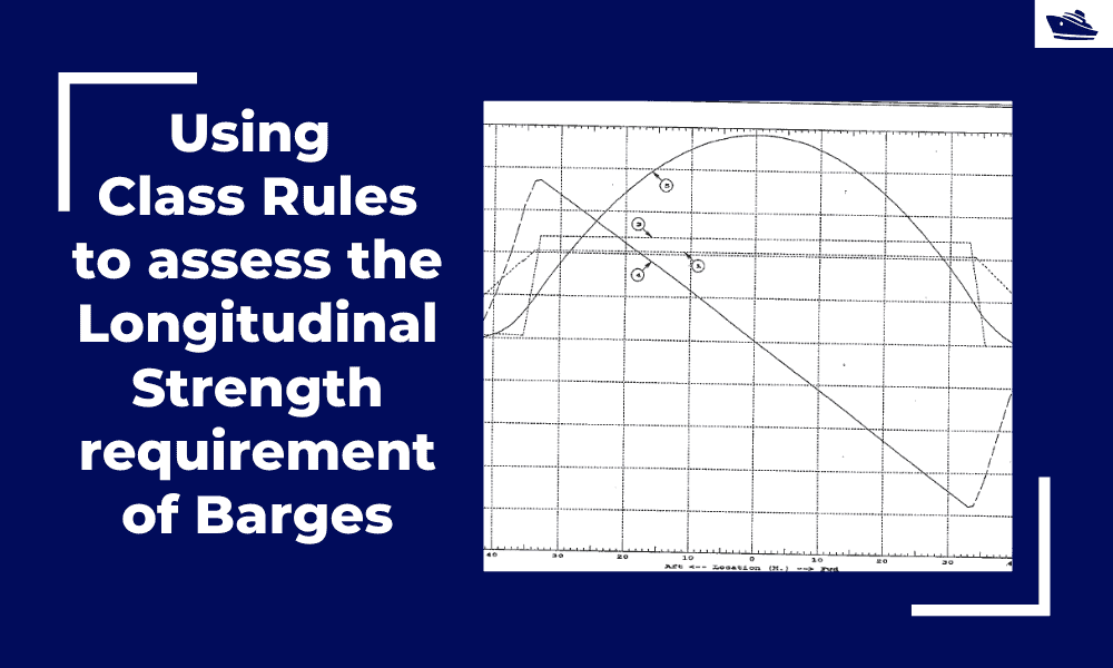
Using Class Rules to assess the Longitudinal Strength requirement of Barges
Introduction The longitudinal strength of a vessel is integral to its evaluation for a given purpose. To get an introduction to the topic, please refer to our other article https://thenavalarch.com/longitudinal-strength-ships-introduction/ In this article, we’ll see...
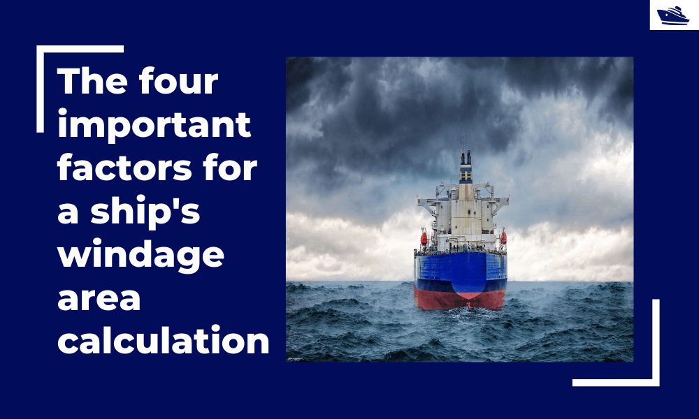
The four important factors for a ship’s windage area calculations
Introduction The windage area of a vessel or offshore structure is the area that is exposed directly to the wind. As is obvious, this is the area of all items above the waterline. This will include Part of the hull/offshore structure above the waterline...
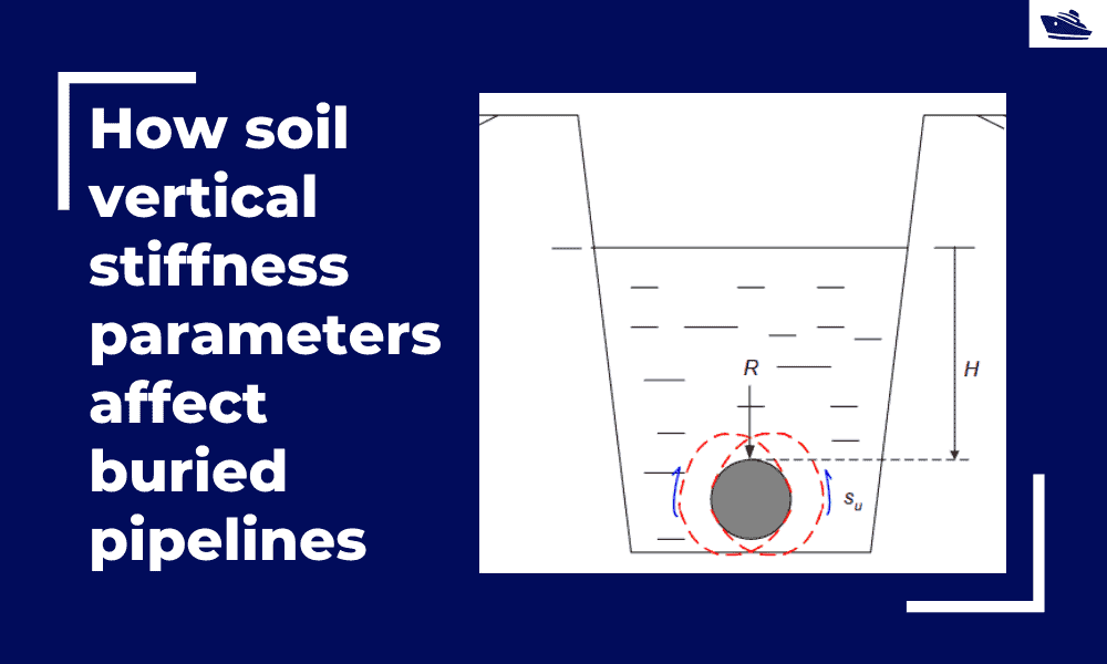
How soil vertical stiffness parameters affect buried pipelines
Introduction Pipe soil interaction is a critical subject of analysis in the field of the offshore industry. A pipe once buried in the seabed is usually in equilibrium with the surrounding soil. There are however various forces which are still in action even if the...
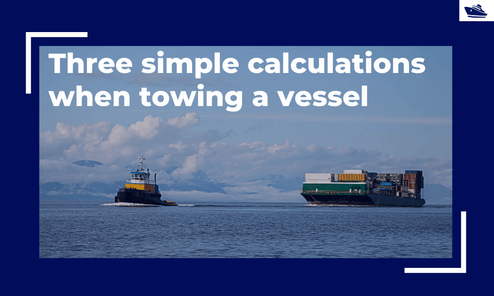
Three simple but useful calculations when towing a Vessel
In this article, we will explore three simple but useful calculations that can be used for towing operations. They are: Towline Stiffness Propeller race Towing bridle force DNV-RP-H1o3, Modelling and Analysis of Marine Operations, FEBRUARY 2014 has been referenced...
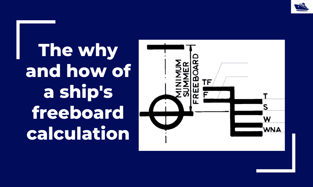
The why and how of freeboard calculation of a ship
Introduction Freeboard is a common term used in vessel operations. Freeboard is the smallest vertical distance between the waterline and the freeboard deck (generally the upper deck) along the length of the vessel. The term ‘smallest’ is of significance, as the height...
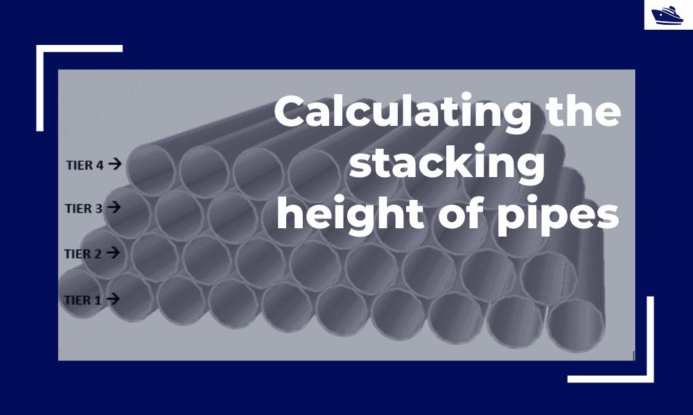
Calculating the maximum stacking height of pipes
Introduction Pipes (or linepipes or joints) are used for multiple purposes and locations in the maritime/offshore industry. Onshore and offshore pipelines are used for transportation of fluids on land, over and underwater. Pipes are fabricated in an onshore facility...
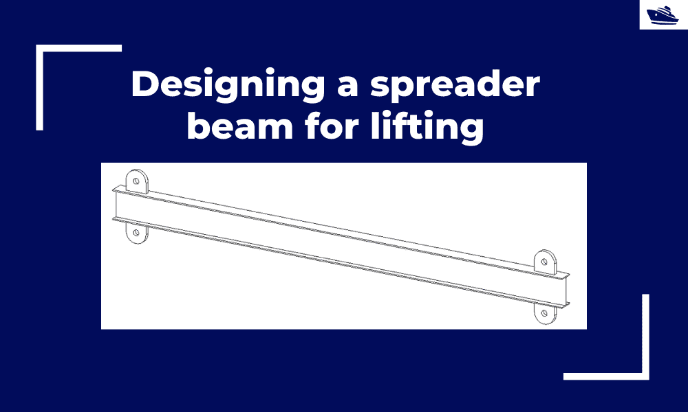
Designing a spreader beam for lifting
Spreader beams are universally applied gear which is widely used in various types of lifting operations, onshore and offshore. In this article, we will explore the design of a basic spreader beam and see what design checks are needed to establish the suitability of a...
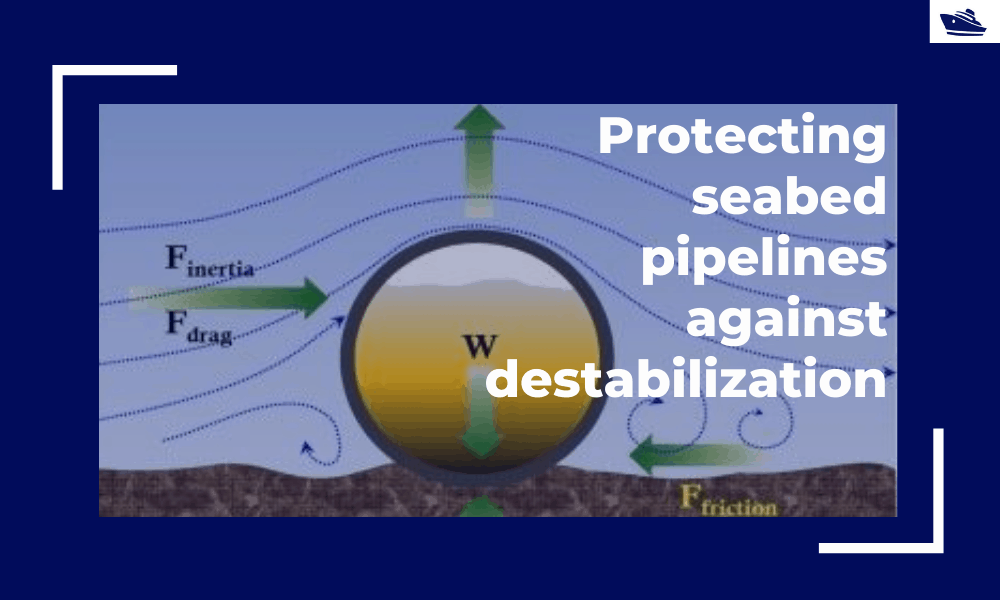
Protecting the seabed pipelines against destabilization: Identifying and qualifying the risk
The Philosophy Cable hydrodynamic stability is one of the most fundamental design topics which are addressed by cable installation engineers. In its simplest form, a simple force balance approach may be considered to ensure that the cable is not displacing...
Safe Towing: Calculating a towline’s catenary and sag
Introduction Towlines connect a tug to the vessel being towed and are defined by multiple characteristics like Weight, Diameter, and Stiffness. The tension in the towline during the towing operation is not static but keeps varying with the distance between the tug and...
Please check out TheNavalArch’s product for planing vessel resistance estimation:

Interesting solution to a practical problem.