by Michael Harwood, PE, PMP
Overview
Lifting by crane is a basic construction operation that dates back to at least Sixth Century BC (ancient Greece for example) and the lifting operation itself dates back much further. It is a very common operation in present-day construction so the design of lift rigging is of much interest.
This article is intended to provide guidance to non-specialists (including knowledgeable designers) in developing slightly conservative preliminary lift rigging designs. It is still recommended (and may indeed be required) that an engineer take responsibility for the final design and indeed is a requirement in many jurisdictions.
Two rigging arrangement options for 4-point, single hook lifts are considered here, namely with and without a spreader bar. Items being lifted are referred to as lift packages. The packages considered here are light to medium weight as the design of heavy lifts is definitely best left to specialists.
Examples lifts utilizing these rigging types are presented below.
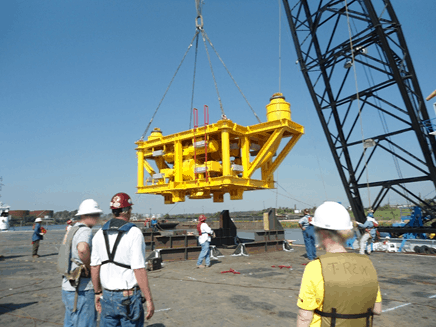
Four point lift without spreader
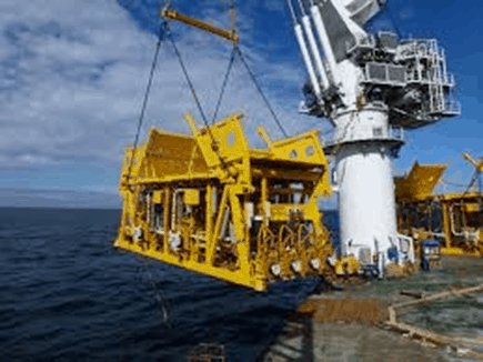 Four point lift with Spreader
.
Preliminary Rigging Design Summary
Preliminary rigging design as described here is summarized in the table below and further described in notes following the table.
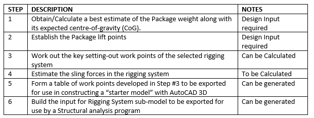
Notes on the above Rigging Design Process
- Re: step #1, one needs to obtain/calculate a best estimate of the Package weight at the time of the planned lift operation. The package weight estimate should include all contingencies and weight allowances. These “uncertainty factors” are necessarily larger at the beginning stages of Package design than at the end of Package construction.
- Also re: step #1, one should obtain/calculate a best estimate of the expected centre-of-gravity (CoG) of the Package. If a formal and rigorous weight control program is not in place, there may be significant uncertainty in the CoG location so variations of this parameter could be considered eg “CoG shift” with respect to the best-estimate CoG location.
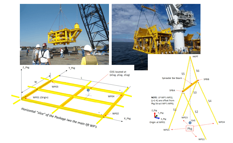
- Re: Step #2, Lift Points for the Package need to be defined. These are generally offset from strong points in the lift package and are taken as the basis working-points (WPs) for the setting-out of the rigging arrangement. These can be the centre of the pad-eye pinholes or intersections of sling line and trunnion centre-line depending on the selected lift point attachment design concept. These are illustrated in the following figure depicting a horizontal slice of the package.
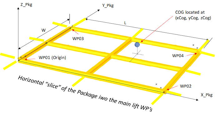
Defining the lift points of the package
- Re: Step #3, the (crane) hook point location needs to be worked out based on rigging system constraints for the planned lift along with the key work points of the spreader bar if applicable. These are based on rigging system constraints eg minimum sling angle, sufficient clearance between rigging system and lifted package components above the lift points and noting that the lift package will orient itself such that the hook point is directly above the CoG of the combined package and rigging system once the package is lifted off the ground. Rigging systems for “With Spreader Bar” and “NO spreader bar” options are presented in the following figure.
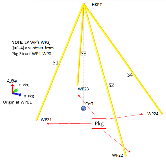
Rigging System with ‘no spreader bar’
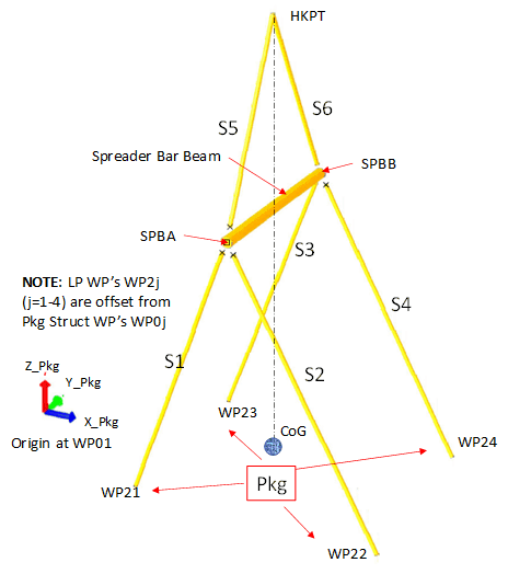
Rigging System ‘with Spreader bar’
- Re: Step #4, estimation of the nominal sling forces can proceed as follows.
- The first step in estimating the nominal sling tension forces is to redistribute the lift weight to the 4 lift points noting that the solution is statically indeterminate. An algorithm based on preserving static equilibrium can be employed which yields an exact solution (though not unique) for a rigid Package when the following three conditions hold: The 4 lift points are coplanar; The 4 lift points form a rectangle and; The Package CoG is located in the same plane as the lift points. The latter condition almost never occurs while the first two are quite common. However, each of the three conditions may be relaxed and the difference between the estimated 4-Tributary weight solution and the single Package weight solution may be compared. Then a decision can be made as to whether to accept the estimated results. For typical cases, it has been observed that the difference is less than 1%.
- The second step is to utilize the four estimated tributary weights to calculate the forces in the slings noting that the rigging system is a pin-jointed lattice similar to a 3D truss structure.
- Also re: Step #4, design of rigging components requires an estimate of the peak sling loads which may occur during the initial lift off the ground. These are subject to uncertainty so the estimated nominal sling loads (due to package weight alone) are typically “factored-up”. In the present method, a “preliminary design lift load factor” (PDLLF) is introduced as a simplification. This factor is a function of Dynamic Amplification Factor, Consequence Factor and Rigging Component Safety Factor as described in various lift design guidelines/codes such as DNVGL-ST-N001. It is noted that the definitions of these factors is not 100% consistent across the various codes/guidelines. Suggested (conservative) choices of PDLLF for preliminary rigging components design are presented in the following table:

Lift Load Factors for different environments
It is noted that the above PDLLF choices are suitable for preliminary design. for final rigging component selection, the governing project lift design code/guideline should be followed where the various factors are applied to the nominal sling loads.
Screenshots of rigging arrangement drawings generated in AutoCA
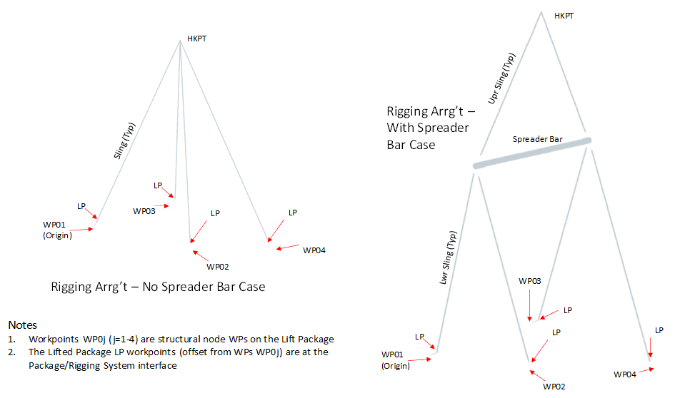
7. Re: Step #5, the calculated WPs may be “exported” for input into a AutoCAD 3D “starter model”. This model is to be further detailed by AutoCAD designers to become a proper rigging arrangement drawing. Main advantage of this approach is that the WP locations are “pre-checked” by the engineer or lead designer who produces the exported WPs. The following figure is composed of AutoCAD screen-shots where the rigging system is represented by lines whose end points are the WPs generated in Step #4.
8. Re: Step #6, one can build the input for a Rigging System sub-model to be incorporated into a Lift Structural analysis and export it to an input file readable by a structural analysis program (eg SACS, Staad Pro) It is noted that the slides presented with Steps #3 and #4 were produced from SACS models.
Available Calculators
An “App” has been developed to automate Steps #1-#4 in the summary procedure above along with a companion App to automate Step #5. These will soon be available from TheNavalArch.com so watch for their upcoming post in your LinkedIn feed and on other marine engineering web sites you may follow. Automation of Step #6 is going through testing with plans to make the features involved available in an upgraded version of the basic Apps.

Michael Harwood
CCnBW at MCHTM Inc
INTRODUCTION:
Forward looking, project-oriented engineer and manager with over 30 years design, analysis and work management/coordination experience mainly in the offshore oil and gas industry. Present focus is on providing customers/employers with designs that are optimized for weight and constructability within cost and schedule constraints. Rapid delivery of these is achieved by automating calculation processes as much as possible, particularly when dealing with interface data from mechanical and piping disciplines. Refer to my recent LinkedIn articles for examples.
CAREER OVERVIEW:
Began as a structural engineering analyst out of university and moved up into hands-on management positions both in operations and projects. Acquired overall knowledge of oil and gas production facilities and gained both US and international experience along the way. Familiar with both owner’s and contractor’s interests so can work as Owner’s Engineer or EPC Contractor PMT member. Became an independent consultant in 2008 working and work through MCHTM Inc or as a contract engineer depending upon what works best for my client. Along the way, have worked on approximately 50 projects and 20 tenders of various durations and produced over 1000 report, drawing, and specification deliverables of varying scope.
GOAL: To have satisfied customers/employers
SPECIALTIES
Specialties: Structural engineering subject matter expert. Expert user of structural analysis computer programs and offshore and ship design codes. Also familiar with subsea equipment structures and installation aids as well as offshore pipeline installation equipment and aids. Brown field and newbuild. Structural engineering planning and management.
Design aid software developer to advance design automation, design work methods planner, construction engineering support. Coach/mentor of junior engineers.
General experience with hull and mooring systems and topsides production facilities on the following offshore platform types: FPSOs; CPTs, Spars; Production Semis; TLPs, MODUs; MOPUs and Fixed Base as well as the following ship types: Drilling, S-lay Pipelay; Naval.

Combating rising seas with floating structures
Introduction Rising sea level is an existential threat for many coastal cities. The sea is rising subtly but relentlessly at an exponential rate. Many predictions of how high and how fast it will rise in the next 50 years have proved to be understated. According to...
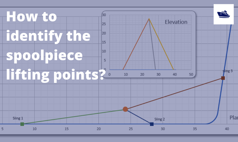
How to identify the spoolpiece lifting points?
In the offshore construction industry, the connection between the newly installed pipeline and the riser is accomplished via a series of ‘spoolpieces’ (or spools). The spool is fabricated by welding pipe joints to form an L-shaped, Z-shaped, or possibly a straight...
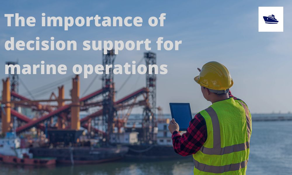
The importance of clear decision support before marine operations
Our oceans are interspersed with human activities: be it fishing, marine transportation, or offshore operations. These operations usually involve assets worth multiple million dollars, be it the produce or the equipment or in most cases, the human life. Produce from...
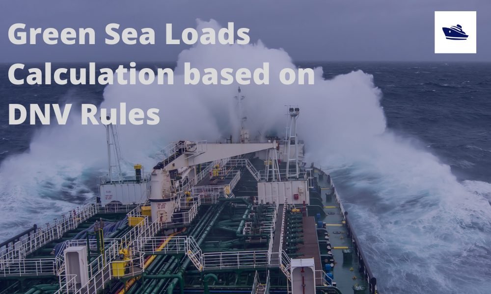
Sea Pressure Loads Calculation based on DNV Rules
Introduction Sea pressure loads are an important factor in the structural design of a vessel. What is sea pressure load? As the term suggests, it is the external pressure on the vessel due to the surrounding sea. What kind of pressure it is, and how to...
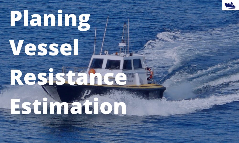
A quick empirical method for resistance estimation of planing vessels
Resistance estimation for a vessel is a fundamental exercise in design of the vessel. Resistance is a property that depends on the vessel’s shape and form. A conventional ship-shaped vessel with a bulb will have completely different resistance characteristics compared...

Powering the maritime industry with Hydrogen – Part 2
Powering the shipping industry with hydrogen - Part 2: Hydrogen propulsion on a ship - opportunities and challenges Introduction In the Part 1 of this article, we explored the basic properties of Hydrogen as a fuel, and also the opportunities and challenges...
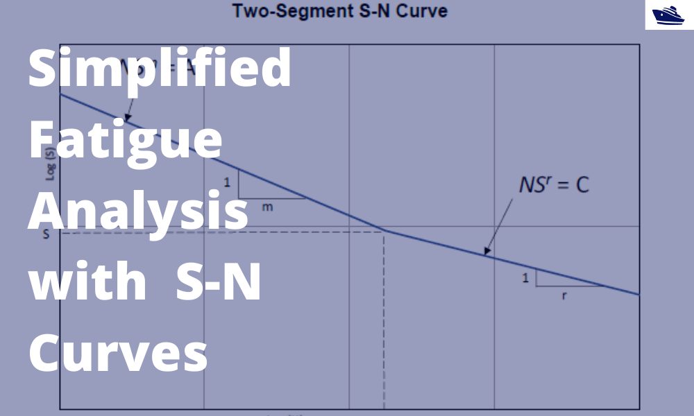
A simplified method of performing fatigue analysis of offshore structures
A simplified method of performing fatigue analysis of offshore structures Introduction An offshore structure is subject to environmental loads of waves, wind and current. By their nature, the resulting wave loads on the structure are cyclical. These cyclical...

Powering the shipping industry with hydrogen: opportunities and challenges (Part 1)
Part 1: About Hydrogen – Basics, Opportunities, and Challenges Of late, hydrogen has been generating quite a buzz in the energy sector with its possibility as a clean source of energy. The shipping sector is not untouched, and this article explores the possibilities...
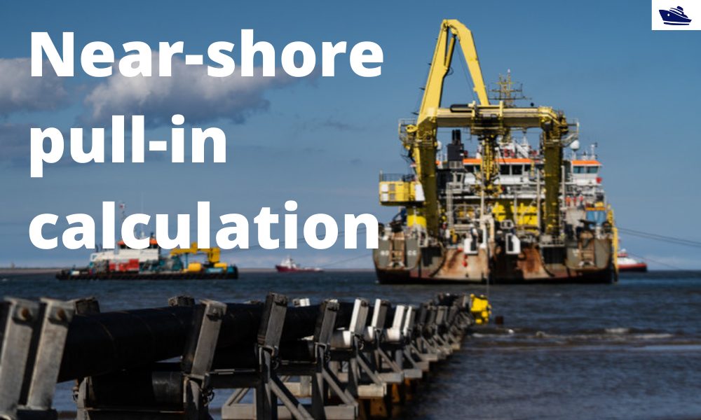
The importance of analysis in nearshore pull-in operation in offshore wind farms
Introduction Over the last 10 years, the global wind energy business has increased manifold. In the next 5 years, the rate of installation is expected to accelerate. This is mostly driven by the opening up of Chinese and US markets. A primary chunk of this market is...

Vessel Draft Survey Accuracy
by Chris Zeringue, Owner, MTS Marine Techincal Surveyors The key to accuracy in a Vessel Draft Survey may very well be found in a hole in the ship. I boarded my...