Introduction
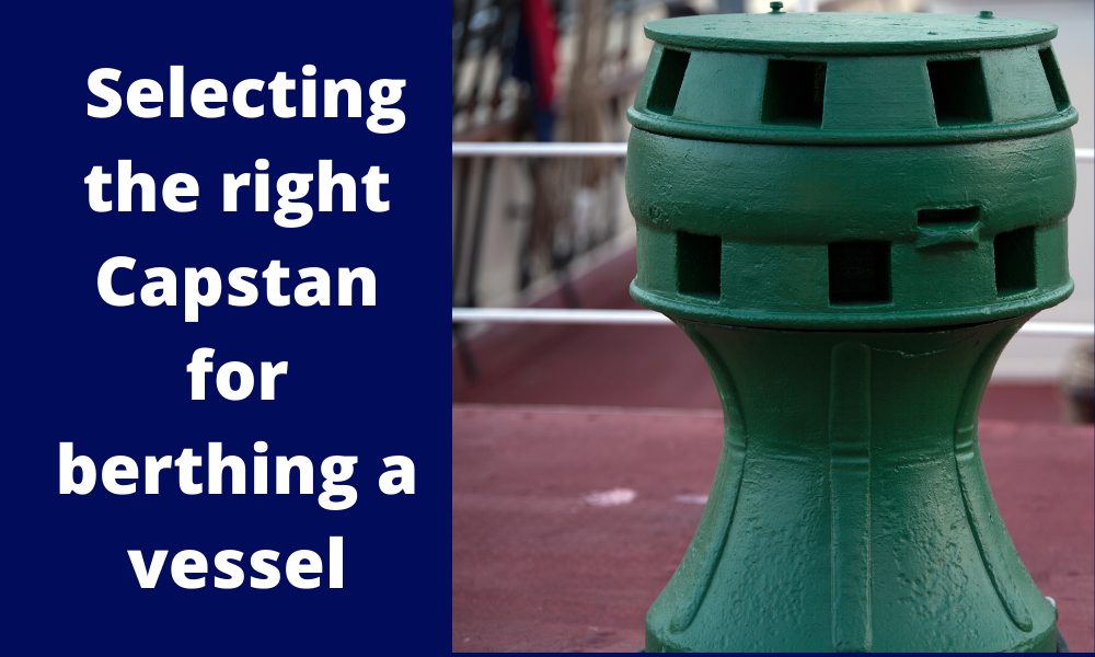
Capstans are frequently deployed mooring equipment used on all types of vessels. Capstans are berthing/mooring equipment used to multiply the pulling force on mooring ropes.
Traditionally, Capstans were operated manually but in modern ships, they are operated wither electro-hydraulically or electromechanically.
When Capstans are used in mooring ships, they have to be sufficient in size and number to overcome the forces which the ship experiences in the lateral direction due to environmental forces of wind and current. How do we know what size capstans will be sufficient? We’ll take a detailed look at in this article.
This article is based on DDS-582-1 Calculations for Mooring Systems, Department of the Navy, Naval Sea Systems Command, Washington DC, 20362-5101.
The Concept
When berthing a vessel, a number of capstans on the vessel may be utilized simultaneously. How do we determine if the capstan size is sufficient?
Thinking in basic terms, the berthing operation of the vessel will impose some forces on the vessel, which are transferred through the berthing lines to the capstans. What forces are these?
At the berth, the two major forces are the wind and current forces that the vessel experiences. Also, since the vessel is mostly berthed sideways, these forces must be calculated on the side of the vessel (not on the front).
The wind and current forces are characterized by the wind and current speed at the berth.
Thus, a simple approach to determine the capstan design will be:
- Calculate the lateral berthing forces (wind and current) on the vessel
- Divide the total lateral berthing force by the number of capstans to get the force per capstan. This will give the required line pull of the capstan
- The capstan power is obtained by dividing the required line pull times the warping speed by the capstan’s efficiency.
Environmental Forces
The first step is calculating the environmental forces on the vessel. Generally, at berth, wind, and current are the most significant forces, while wave forces can be generally ignored.
When calculating the wind and current forces, the standard physics formula of Force = Pressure x Area shall be used. In the method by DDS-582 (Ref 3), wave forces have not been considered for doing the calculation.
For wind force, the formula is Fwind = 1/2 x Cwind x ρwind x Vwind2 x Awind, where Cwind is the coefficient of wind force, ρwind is the density of air, Vwind is the wind speed, and Awind is the total area of ship and cargo which is exposed to the wind from beam direction (the above-water area)
Similarly, for current force, the formula is Fcurrent = 1/2 x Ccurrent x ρwater x Vcurrent2 x Aunderwater, where Ccurrent is the coefficient of current force, ρwater is the density of water, Vcurrent is the current speed, and Aunderwater is the total underwater area of ship which is exposed to the current from beam direction.
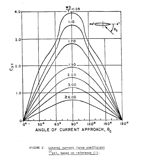
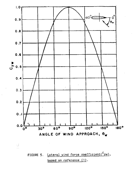
The critical items in the calculations for Wind and Current forces are the force coefficients for wind and current.
These coefficients can be obtained from the coefficient plots provided in DDS-582, and some plots are presented below:
Lateral Current Coefficient (DDS-582)
Lateral Wind Coefficient (DDS-582)
We can see that the lateral current force is dependent on an additional factor: the underkeel clearance which is measured as Water Depth to Draft ratio (WD/T).
At the end of this exercise, we’ll have the following with us:
- Wind Force – transverse
- Current force – transverse
Next exercise is using these forces and calculate the capstan line pull using the environmental forces.
Capstan Design
Once we have the wind and current lateral forces, we add them up together to give the total lateral force on the vessel.
Total Lateral Force, FY = FYW + FYC, where
FY = total lateral force on the vessel
FYW = lateral wind force on the vessel
FYC = lateral current force on the vessel
If the number of capstans is ‘n’, then the line pull per capstan is given by:
PCP = FY/n
Once the line pull is available, the minimum required Capstan power is determined as follows:
PCAPSTAN = PCP x VCP/ηCAPSTAN
Here,
PCAPSTAN = Required minimum capstan power
VCP = Capstan’s warping line speed
ηCP = Capstan’s efficiency
The Capstan’s efficiency has the following components:
- Capstan Head Efficiency
- Overall bearing and gear efficiency
- For electro-hydraulic capstans additionally – Efficiency of Hydraulic Pump and Motor
From the above process, we can obtain the minimum required Capstan’s power using which we can select the right capstan, or we can evaluate the suitability of an existing capstan for berthing.
TheNavalArch has its own app for selecting the right capstan. Do check it out from the link below.
References
- https://en.wikipedia.org/wiki/Capstan_(nautical)
- https://www.brighthubengineering.com/seafaring/51281-what-is-a-capstan-on-a-ship/
- DDS-582-1 Calculations for Mooring Systems, Department of the Navy, Naval Sea Systems Command, Washington DC, 20362-5101
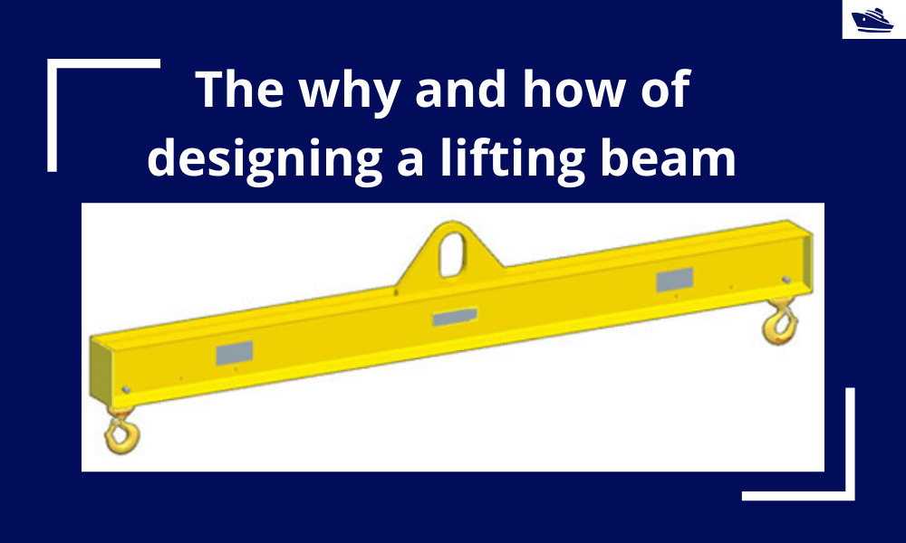
The why and how of designing a lifting beam
Lifting beams are universally applied gear used widely in various types of lifting operations, onshore and offshore. In this article, we will explore the design of a basic lifting beam and see what design checks are needed to establish the suitability of the beam for...
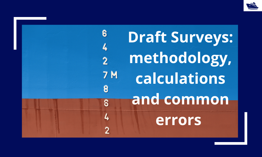
Draft Surveys: Methodology, Calculations, and common errors
Introduction Marine transport is the backbone of the global trade and reasonably can be considered to be the artery of the global manufacturing supply chain, as more than four fifths of the world merchandise trade by volume is carried by sea. Undoubtfully, the...
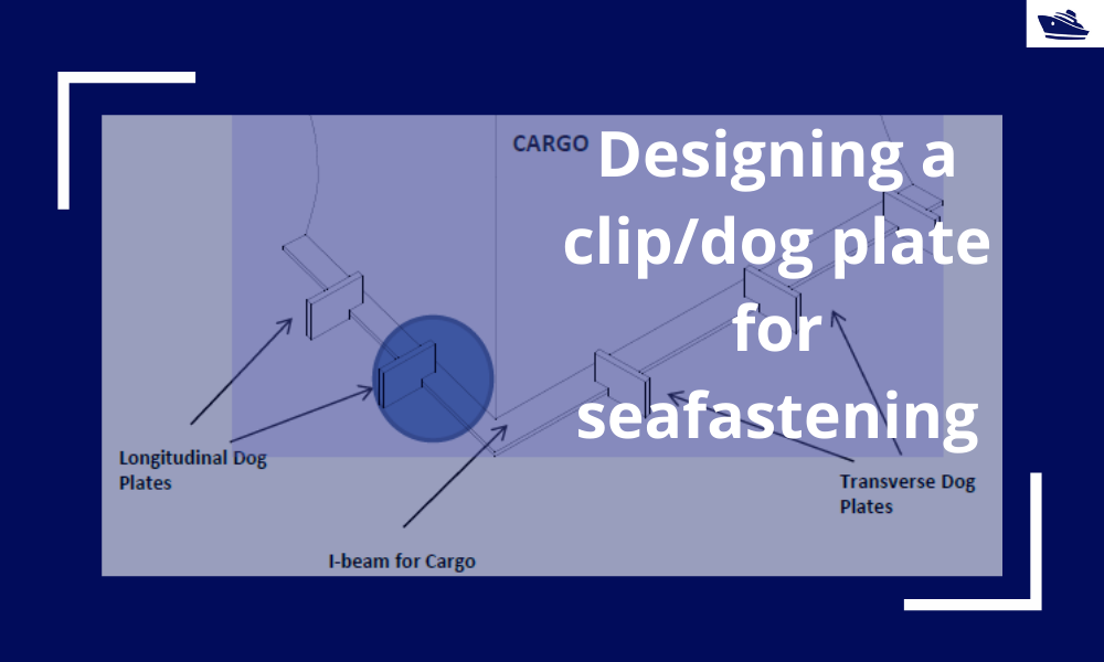
Designing a clip/dog plate for seafastening
Introduction In an earlier article, we saw how to design stoppers for seafastening. Stoppers are items that are used to contain the translation movements (longitudinal and transverse directions) of a cargo on the deck/hold of a vessel. That brings us to the question –...
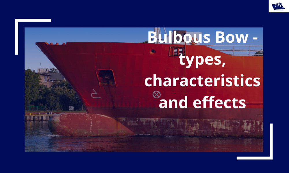
The Bulbous Bow – types, characteristics, and effects
This is Part 2 of the two-part series on Bulbous Bows. For Part 1, click here By Tamal Mukherjee, *This article originally appeared in May 2019 edition of Marine Engineers Review (India), the Journal of Institute of Marine Engineers India. It is being...
Marine Propeller and Shafting Alignment – Part 2
Gap & Sag Alignment Gap and Sag Alignment is carried out to bring the engine to its final position, in case of directly coupled installations, and to bring the gear box to its final position in case of installations with reduction boxes. The figure below indicates...
Marine Propeller Shafting and Shafting Alignment – Part 1
*****This article first appeared in July 2018 edition of Marine Engineers' Review (MER), India. We're reproducing it for the readers of our blog***** Abstract: Since 2013, Shaft Alignment Practice has undergone a change, with developments of Analysis tools. At the...
Using Class Rules to assess the Longitudinal Strength requirement of Barges
Introduction The longitudinal strength of a vessel is integral to its evaluation for a given purpose. To get an introduction to the topic, please refer to our other article https://thenavalarch.com/longitudinal-strength-ships-introduction/ In this article, we’ll see...
The four important factors for a ship’s windage area calculations
Introduction The windage area of a vessel or offshore structure is the area that is exposed directly to the wind. As is obvious, this is the area of all items above the waterline. This will include Part of the hull/offshore structure above the waterline...
Three simple but useful calculations when towing a Vessel
In this article, we will explore three simple but useful calculations that can be used for towing operations. They are: Towline Stiffness Propeller race Towing bridle force DNV-RP-H1o3, Modelling and Analysis of Marine Operations, FEBRUARY 2014 has been referenced...
The why and how of freeboard calculation of a ship
Introduction Freeboard is a common term used in vessel operations. Freeboard is the smallest vertical distance between the waterline and the freeboard deck (generally the upper deck) along the length of the vessel. The term ‘smallest’ is of significance, as the height...

Work as a Project Engineer at Colombo Dockyard PLC for New Building Projects
Comment *Looks like an interesting article