Introduction
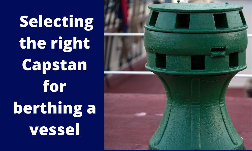
Capstans are frequently deployed mooring equipment used on all types of vessels. Capstans are berthing/mooring equipment used to multiply the pulling force on mooring ropes.
Traditionally, Capstans were operated manually but in modern ships, they are operated wither electro-hydraulically or electromechanically.
When Capstans are used in mooring ships, they have to be sufficient in size and number to overcome the forces which the ship experiences in the lateral direction due to environmental forces of wind and current. How do we know what size capstans will be sufficient? We’ll take a detailed look at in this article.
This article is based on DDS-582-1 Calculations for Mooring Systems, Department of the Navy, Naval Sea Systems Command, Washington DC, 20362-5101.
The Concept
When berthing a vessel, a number of capstans on the vessel may be utilized simultaneously. How do we determine if the capstan size is sufficient?
Thinking in basic terms, the berthing operation of the vessel will impose some forces on the vessel, which are transferred through the berthing lines to the capstans. What forces are these?
At the berth, the two major forces are the wind and current forces that the vessel experiences. Also, since the vessel is mostly berthed sideways, these forces must be calculated on the side of the vessel (not on the front).
The wind and current forces are characterized by the wind and current speed at the berth.
Thus, a simple approach to determine the capstan design will be:
- Calculate the lateral berthing forces (wind and current) on the vessel
- Divide the total lateral berthing force by the number of capstans to get the force per capstan. This will give the required line pull of the capstan
- The capstan power is obtained by dividing the required line pull times the warping speed by the capstan’s efficiency.
Environmental Forces
The first step is calculating the environmental forces on the vessel. Generally, at berth, wind, and current are the most significant forces, while wave forces can be generally ignored.
When calculating the wind and current forces, the standard physics formula of Force = Pressure x Area shall be used. In the method by DDS-582 (Ref 3), wave forces have not been considered for doing the calculation.
For wind force, the formula is Fwind = 1/2 x Cwind x ρwind x Vwind2 x Awind, where Cwind is the coefficient of wind force, ρwind is the density of air, Vwind is the wind speed, and Awind is the total area of ship and cargo which is exposed to the wind from beam direction (the above-water area)
Similarly, for current force, the formula is Fcurrent = 1/2 x Ccurrent x ρwater x Vcurrent2 x Aunderwater, where Ccurrent is the coefficient of current force, ρwater is the density of water, Vcurrent is the current speed, and Aunderwater is the total underwater area of ship which is exposed to the current from beam direction.
The critical items in the calculations for Wind and Current forces are the force coefficients for wind and current.
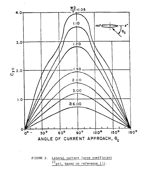
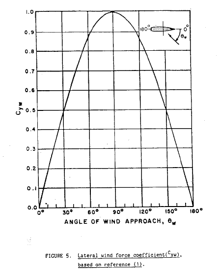
These coefficients can be obtained from the coefficient plots provided in DDS-582, and some plots are presented below:
Lateral Current Coefficient (DDS-582)
Lateral Wind Coefficient (DDS-582)
We can see that the lateral current force is dependent on an additional factor: the underkeel clearance which is measured as Water Depth to Draft ratio (WD/T).
At the end of this exercise, we’ll have the following with us:
- Wind Force – transverse
- Current force – transverse
Next exercise is using these forces and calculate the capstan line pull using the environmental forces.
Capstan Design
Once we have the wind and current lateral forces, we add them up together to give the total lateral force on the vessel.
Total Lateral Force, FY = FYW + FYC, where
FY = total lateral force on the vessel
FYW = lateral wind force on the vessel
FYC = lateral current force on the vessel
If the number of capstans is ‘n’, then the line pull per capstan is given by:
PCP = FY/n
Once the line pull is available, the minimum required Capstan power is determined as follows:
PCAPSTAN = PCP x VCP/ηCAPSTAN
Here,
PCAPSTAN = Required minimum capstan power
VCP = Capstan’s warping line speed
ηCP = Capstan’s efficiency
The Capstan’s efficiency has the following components:
- Capstan Head Efficiency
- Overall bearing and gear efficiency
- For electro-hydraulic capstans additionally – Efficiency of Hydraulic Pump and Motor
From the above process, we can obtain the minimum required Capstan’s power using which we can select the right capstan, or we can evaluate the suitability of an existing capstan for berthing.
TheNavalArch has its own app for selecting the right capstan. Do check it out from the link below.
References
- https://en.wikipedia.org/wiki/Capstan_(nautical)
- https://www.brighthubengineering.com/seafaring/51281-what-is-a-capstan-on-a-ship/
- DDS-582-1 Calculations for Mooring Systems, Department of the Navy, Naval Sea Systems Command, Washington DC, 20362-5101

Calculating the maximum stacking height of pipes
Introduction Pipes (or linepipes or joints) are used for multiple purposes and locations in the maritime/offshore industry. Onshore and offshore pipelines are used for transportation of fluids on land, over and underwater. Pipes are fabricated in an onshore facility...
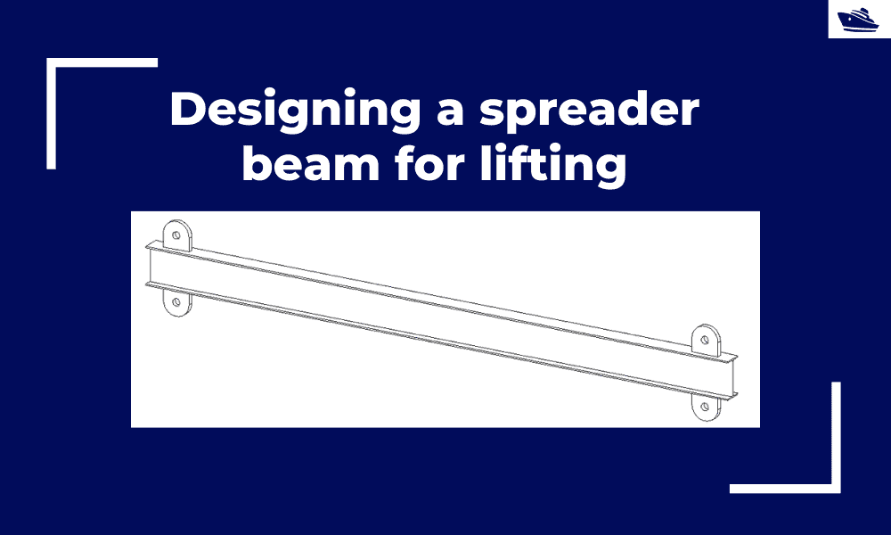
Designing a spreader beam for lifting
Spreader beams are universally applied gear which is widely used in various types of lifting operations, onshore and offshore. In this article, we will explore the design of a basic spreader beam and see what design checks are needed to establish the suitability of a...
Safe Towing: Calculating a towline’s catenary and sag
Introduction Towlines connect a tug to the vessel being towed and are defined by multiple characteristics like Weight, Diameter, and Stiffness. The tension in the towline during the towing operation is not static but keeps varying with the distance between the tug and...
Designing the lashings of deck cargo using IMO CSS
Introduction More than 70% of the earth is covered by water, which makes shipping historically the easiest and cheapest way of connecting manufactures and customers across the globe and can be reasonably considered to be the artery of the global economy....

Using MS Excel to evaluate the Stability of existing Barges
Barges are the simplest, and yet most widely used of marine vehicles. They are used for a variety of purposes ranging from carrying cargo in bulk or liquid, to even carrying passengers for short inland cruises. Barges are mostly towed by another barge called a tug,...
The importance of ULS (Ultimate Longitudinal Strength) and how to assess it for a damaged hull
by Alessandro La Ferlita, Naval Architect Ultimate hull girder strength represents the maximum capacity, of the hull girder beyond the structure fails. In fact, if the vertical bending moment applied overcomes a certain maximum value, the ship can collapse (Figure 1)...
How to calculate the strength of Midship Section of a Ship
The mid-ship section of a ship is a defining structural drawing of the vessel. It represents the most critical structural parameter of the vessel – its global strength. To assess how much of the bending moment (hog and sag) the vessel can tolerate, it is important to...
How to use empirical formulas to estimate the resistance of a Ship
How to use empirical formulas to estimate the resistance of a Ship Resistance estimation holds immense importance in the design stage of a vessel. Based on the results of the resistance estimation of a vessel, the selection of the right propulsion system is done....
Designing the berth mooring of your vessel with this simple yet effective method
A vessel at berth experiences much lower forces compared to a vessel in the open sea due to the milder environment, but it still requires a mooring configuration suited to the forces it experiences, and also suitable for the type of berthing configuration adopted. The...

Bulbous Bows – History and Design
by Bijit Sarkar, Naval Architect Introduction The eternal search of a naval architect – a perfect bow. Sadly, it never exists. Different bow forms are good for different types, sizes of vessels and seaways. What does a naval architect want out of the bow he designs?...

Work as a Project Engineer at Colombo Dockyard PLC for New Building Projects
Comment *Looks like an interesting article