Introduction
The longitudinal strength of a vessel is integral to its evaluation for a given purpose. To get an introduction to the topic, please refer to our other article
https://thenavalarch.com/longitudinal-strength-ships-introduction/
In this article, we’ll see from a regulatory (Classification) perspective, what the important factors determining Longitudinal Strength requirements for barges are.
Longitudinal Strength determines the global strength characteristics of the Barge. Referring to our previous article, considering the ship as a simply supported beam, the strength will depend on the strength of the structural cross-section of the ship. Most of the time, the midship structural section is considered the representative for the barge’s strength as the maximum bending moment is expected at midship.
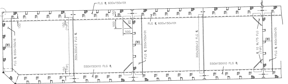
A midship section of a Barge is shown below:
Also, a typical bending moment diagram of a barge is shown below:
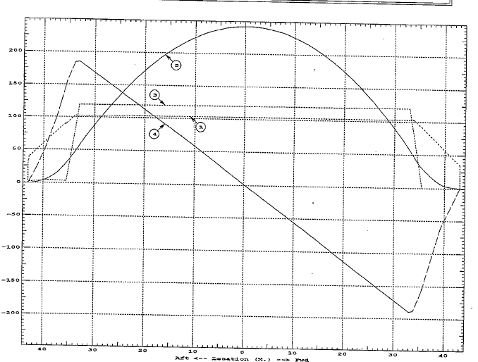
We can see that the midship section is the critical one since the bending moment amidships is the largest
What parameter determines the strength of the midship section of the Barge?
Beam analogy
Considering the beam analogy, the strength of the beam depends upon the section property of the beam. In short, the bending stress on the beam is given by:
Bending Stress = Bending Moment/Section Modulus
Thus, the defining parameter that dictates the beam’s strength is its Section Modulus.
How do we calculate the Section Modulus of the midship section (or any other section) of the ship?
The calculation of section modulus is investigated in another related article:
https://thenavalarch.com/how-to-calculate-the-strength-of-midship-section-of-a-ship/
The role of Classification Rules
Once we have calculated the section modulus of the midship section of the Barge, how do we know if it is sufficient? How do we know what should be the minimum section modulus for the Barge to be fit to ply in the open ocean?
The requirements for minimum strength characteristics are provided by regulatory bodies (a.k.a. Classification Societies like ABS, DNV, LR, IRS, CCS, etc.)
In this article, we’ll see from a regulatory perspective (i.e., Ship Classification) the requirements for longitudinal strengths of Barges.
We will refer to the American Bureau of Shipping (ABS) Rules for Building and Classing Steel Barges, 2020 for this article. It is to be noted that these rules apply to ocean-going barges with a Breadth-to-Depth ratio of up to 4.
The Classification rules help by providing the minimum requirements that the vessel must meet.
With regard to the longitudinal strength of Barges, the two important parameters that the rules have laid out are:
- Minimum Section Modulus amidships
- Minimum Hull girder moment of Inertia amidships
Minimum Section Modulus amidships
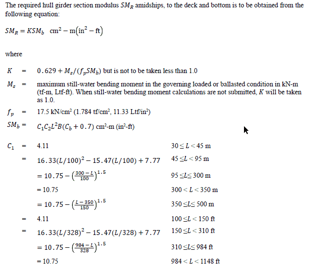
The minimum section modulus requirement is specified in the American Bureau of Shipping (ABS) Rules for Building and Classing Steel Barges, 2020, Part 3, Ch.2, Section 1, 3.1
ABS-Barge-Rule-Long-Strength-2
The required Section Modulus amidships (SMR) is given by
SMR = K SMb
where
SMb = C1C2L2B (Cb + 0.7) cm2-m (in2-ft)
- C1 is a coefficient dependent of the length of the barge, and is higher or longer vessels
- C2 is a constant (0.01)
- K = 0.629 + Ms/(fp SMb) but is not to be taken less than 1.0
Ms = maximum still-water bending moment in the governing loaded or ballasted condition in kN-m (tf-m, Ltf-ft). When still-water bending moment calculations are not submitted, K will be taken as 1.0.
- fp = 17.5 kN/cm2(1.784 tf/cm2, 11.33 Ltf/in2)
The factor K
As highlighted earlier, the bending stress on the midship section is given by
Bending Stress = Bending Moment / Section Modulus
Putting it the other way round,
Section Modulus = Bending Moment/Bending Stress
Thus, if we know the maximum bending moment that the vessel experiences and we know the limit of the bending stress of the material used, we can find out the minimum section modulus that the vessel requires.
The maximum still water bending moment that the vessel experiences can be obtained from the stability booklet, in which the full-load and ballast conditions, including any additional condition (critical in terms of long strength), are included. The highest still water bending moment of all these conditions is used for the calculation of K. When bending moment calculations are not available, K is to be taken as 1.
The still water bending moment (SWBM) calculations are mandatorily required to be submitted if the Barge is of length 76 m or more.
fp is simply the allowable bending stress of the material used and translates to 175 MPa for mild steel, which is 75% of the yield strength of steel.
Minimum Section Modulus amidships
The moment of inertia amidships is derived from the required section modulus, and is given by (Ref [1], 3-2-1, Sec 5):
I = 0.03SMRL cm2-m2 (in2-ft2)
where
L = length of the barge as defined in 3-1-1/3
SMR = hull girder section modulus required for the barge per 3-2-1/3.1, in cm2-m (in2-ft)
High Strength Material
The above rules are applicable to the case when the hull material is Mild Steel. If high strength materials are used for either the upper or lower flanges of the hull girder or both, then a reduction factor is used in the calculation of the required Section Modulus (Ref [1], 3-2-1, Sec 11.3):
SMhts = Q (SMR)
where
Q = 0.78 for H32 strength steel
Q = 0.72 for H36 strength steel
H32, H36 = as specified in Section 2-1-3 of the ABS Rules for Materials and Welding (Part 2)
Wave Bending Moment
Besides the still water bending moment, the vessel also experiences Wave Bending moment in seas. The wave bending moment is considered when there are additional buckling calculations to be submitted to verify the scantlings of the vessel. To account for the wave bending moment in calculations of the factor K, the bending moment used is
Bending moment = Still Water Bending Moment + Wave Bending Moment
The formula used for wave bending moment is
Wave bending moment = Sw x SMb, where Sw = 11.0 kN/cm2, or 110 MPa.
Considering the above, the formula for K becomes
K = 0.629 + (Sw x SMb + MS)/(fp x SMb) = 0.629 + {Sw/fp + Ms/(fp x SMb)}
Thus, it is important to calculate the K factor accurately in order to get a reliable value for the required section modulus for the vessel.
That sums up this article about using Class rules to assess the longitudinal strength of Barges. The required section modulus is an important starting point to design the structural section of the vessel by selecting the right strength elements.
References
[1] ABS RULES FOR BUILDING AND CLASSING STEEL BARGES, JULY 2020
[2] ABS Rules for Materials and Welding (Part 2), July 2020
Disclaimer: This post is not meant to be authoritative writing on the topic presented. thenavalarch bears no responsibility for the accuracy of this article, or for any incidents/losses arising due to the use of the information in this article in any operation. It is recommended to seek professional advice before executing any activity which draws on information mentioned in this post. All the figures, drawings, and pictures are property of thenavalarch except where indicated, and may not be copied or distributed without permission.
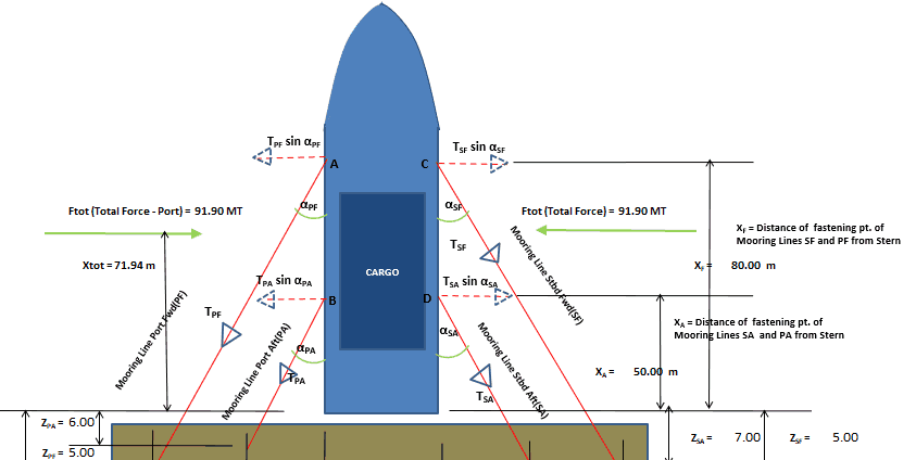
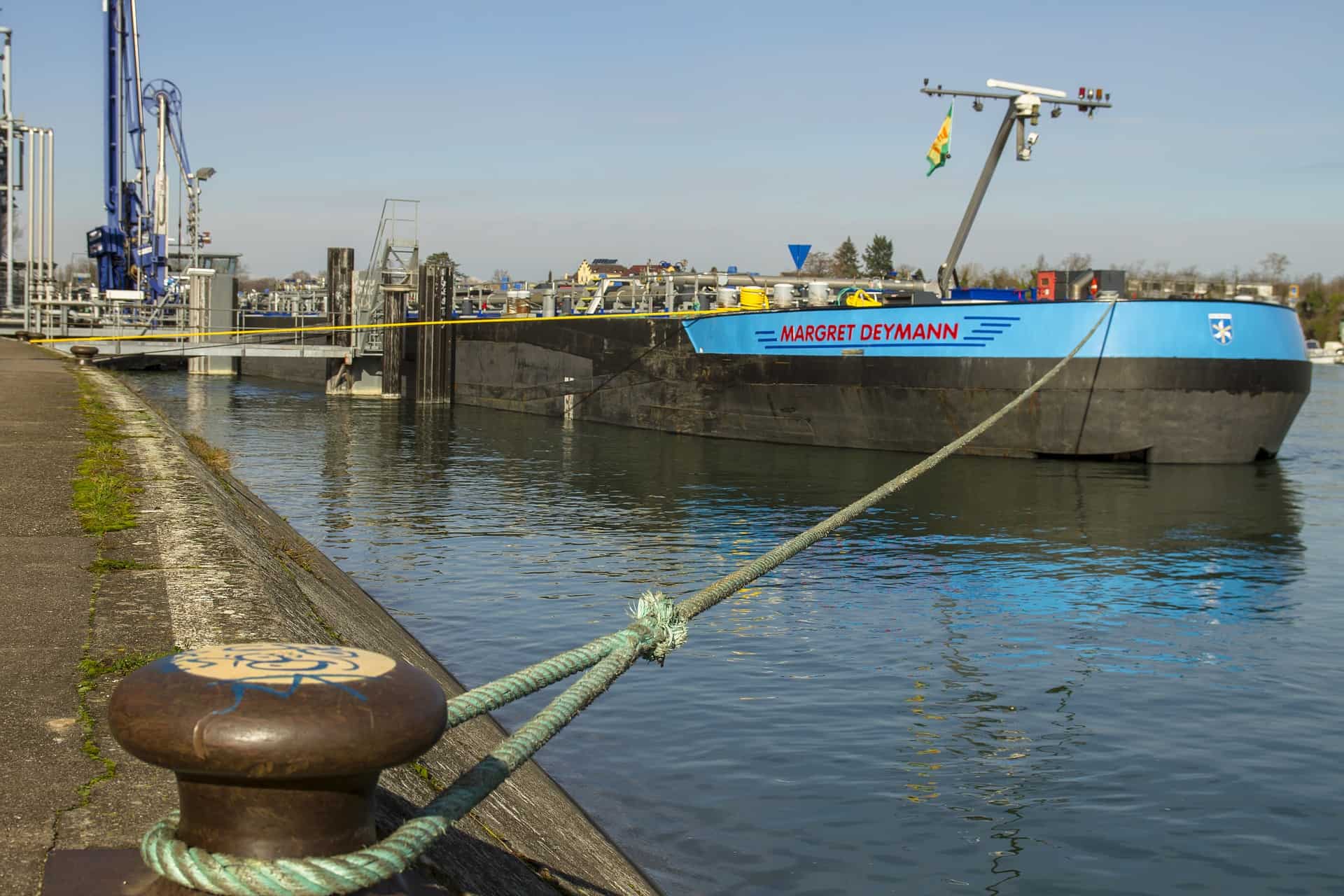
Vessel with Stern on Quay: A simplified method for mooring design
A vessel at berth experiences much lower forces compared to a vessel in the open sea due to the milder environment, but it still requires a mooring configuration suitable to the forces it experiences, and also suitable for the type of berthing configuration adopted....
Cathodic Protection – Ships, Offshore Platforms, FPSO’s and Pipelines: a comparison
Cathodic protection of a structure is an exercise which requires close study of the structure on which it is going to be implemented. The type and quantity of cathodic protection by anodes will depend upon multiple factors: the Geometry of the Structure, the...
Role of a naval architect – a walkthrough (Part – 1)
This is the first in a series of articles on 'Role of a Naval Architect' by Mr Bijit Sarkar, a Naval Architect with 35+ years of experience in ship design and shipbuilding. I would define a naval architect as one who has the ability to greet the client as he/she walks...
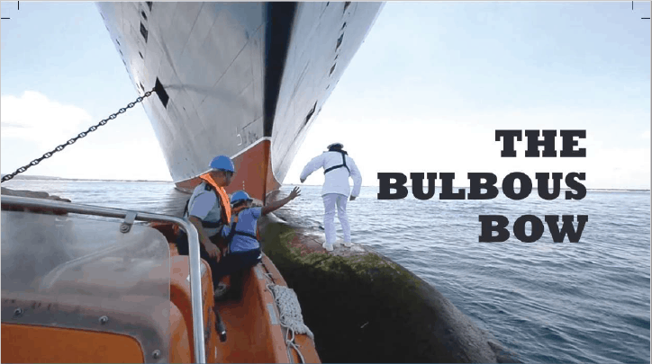
The bulbous bow – why some ships have it and others don’t
By Tamal Mukherjee, This is the Part 1 of a two part article on the Bulbous Bow. Part 2 can be accessed here *This article originally appeared in May 2019 edition of Marine Engineers Review (India), the Journal of Institute of Marine Engineers India. It is being...
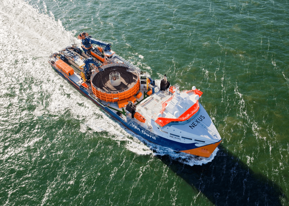
Mitigating risks during subsea cable installation
Over the last 20 years, the interest in offshore wind power generation has increased substantially. Offshore Wind Energy currently provides only 0.3% of world power generation, but the potential is really vast. In the next 20 years the offshore wind industry is set to...
A simple method of selecting the right anchor for mooring a tanker/gas carrier
Anchoring is a fundamental and sensitive operation for a vessel. When a vessel is at anchor, it swings to align itself along the direction of the dominant environment. The anchor is supposed to hold the vessel in varying environmental conditions depending on where the...
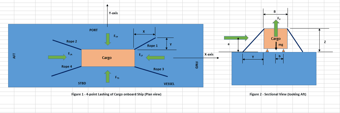
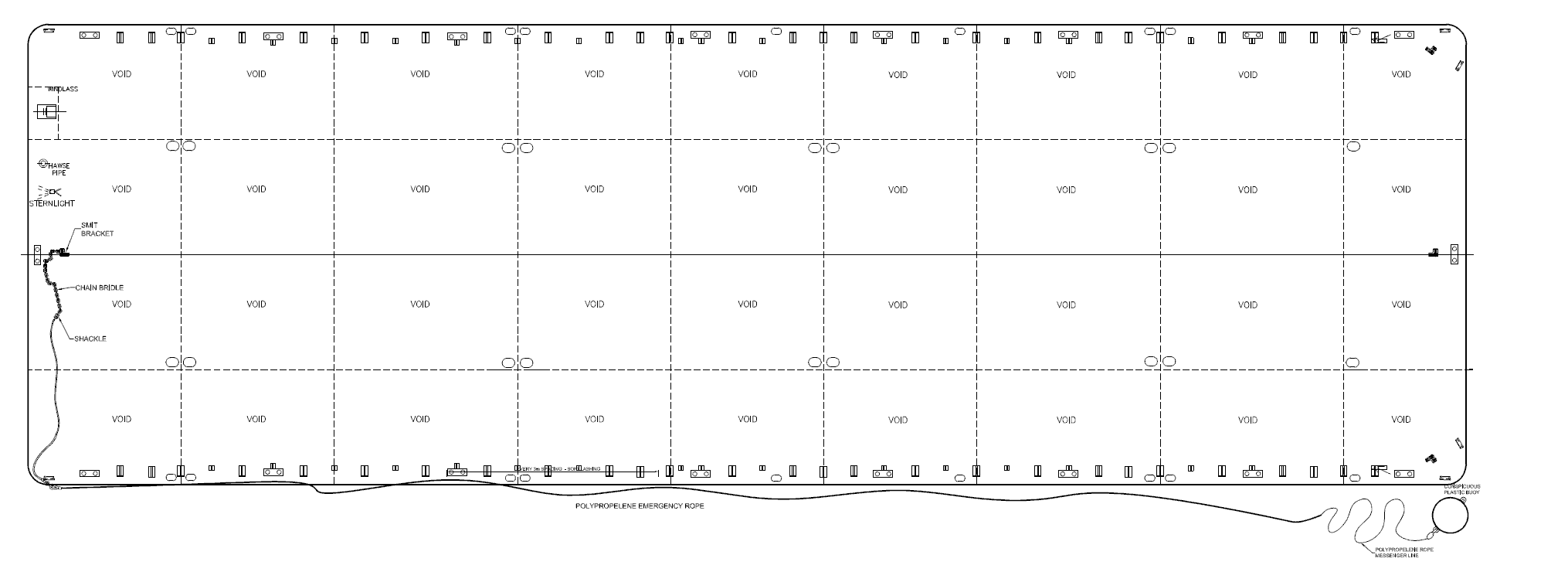
Designing a simple 4-point lashing system for a Deck Cargo
Introduction Lashing of a deck cargo on a ship involves different means and mechanisms to secure the cargo to the deck of the ship. This ‘securing’ is important to contain the movement of the cargo in view of the ship motions during the transportation. The simplest...
Calculating a Ship’s Design MBL using OCIMF MEG-4
In Part 1 of this article, we saw a step by step guide to calculate the Environmental forces on a vessel based on “Standard” environmental criteria defined in Section 3 of OCIMF Mooring Equipment Guidelines Fourth Edition (MEG-4) in order to determine the ship’s...
Selecting the right equipment for towing operations – Emergency Towing
In Part 1 of the article, we discussed the regular towing arrangements and how to select the towing gear for the same. In this part, we will discuss the components of the emergency towing arrangement and how to select them. The purpose of emergency towing equipment is...
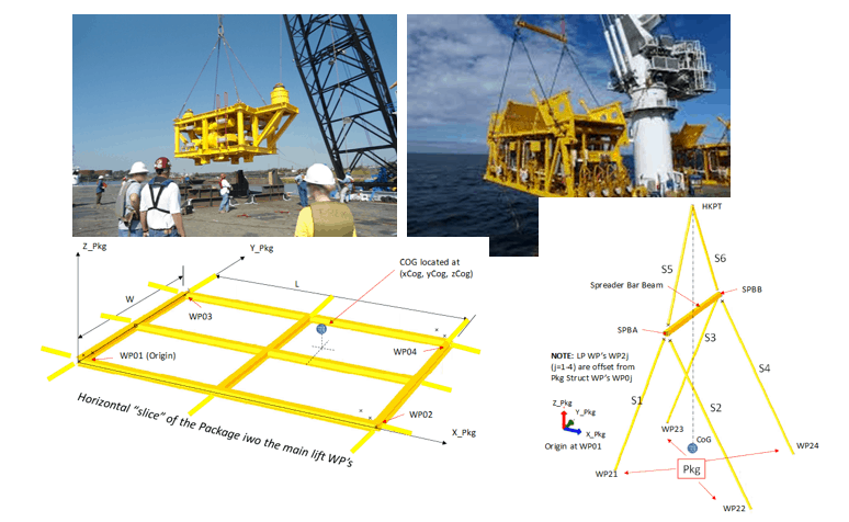
Preliminary Rigging Arrangement Design OF 4 point, Single Hook Lifts for Non-Specialists
by Michael Harwood, PE, PMP Overview Lifting by crane is a basic construction operation that dates back to at least Sixth Century BC (ancient Greece for example) and the lifting operation itself dates back much further. It is a very common operation in present-day...

Nice content. There is need to understand the first principles first to appreciate every parameter and models highlighted in this article. Thank you for putting this together.