Resistance estimation for a vessel is a fundamental exercise in design of the vessel. Resistance is a property that depends on the vessel’s shape and form. A conventional ship-shaped vessel with a bulb will have completely different resistance characteristics compared to a high-speed planing vessel.
Resistance estimates are done using various methods – by hydrodynamic modeling/CFD analyses or by model testing for accurate estimates, or by using empirical relations in the preliminary design phase for a fair estimate of the resistance.
Empirical relations too vary depending on the vessel type. While Holtrop-Mennen method is the most popular one that is used for conventional ship forms (usually merchant vessels), it does not apply to high-speed hulls and planing boats.
Planing vessel resistance calculator – TheNavalArch
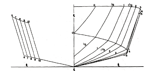
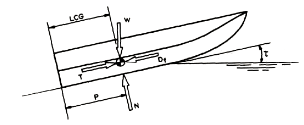
A planing vessel is distinguished form a conventional displacement vessel by the mechanism of weight support. While for a displacement vessel, the buoyancy of the vessel supports its weight, a planing vessel supports its weight by the hydrodynamic lift forces generated when the vessel moves at high speed over water. When the planing vessel is at rest or at low speeds, its weight is supported by its buoyancy, but as it moves with higher speeds, hydrodynamic lift forces are generated by the specially designed hull shape of the planing craft and these lift forces fully support the hull. In some crafts the lift and buoyancy both support the weight. A typical body plan of a planing craft is shown below:
In this article, we will look into a theoretical approach to estimating a planing craft’s performance. A number of resistance tests have been performed by Savitsky (1964) to determine formula for lift and drag of planing vessels, and empirical relations have been provided for the drag.
In this method, at equilibrium, part of the lift is generated by Buoyancy while the rest is generated as hydrodynamic lift. The important parameters of the vessel like its dimensions, speed, displacement etc are taken as inputs, and parameters like trim angle, wetted length of the keel etc. are determined. These parameters are then used to determine the resistance of the vessel.
The method and steps can be broken down into the following:
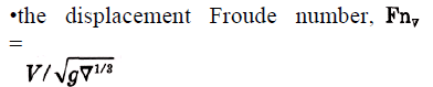
- Step 1 – Calculate the Displacement Froude number: The first parameter to be calculated is the displacement Froude number. It is defined thus
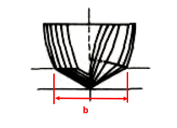
- Step 2 – Calculate the Froude number based on ‘b’: Here, ‘b’ is the maximum beam of the vessel over chine or spray strips. This is the beam of the planing area of the vessel
CV = V/√(gb)
Planing vessel resistance calculator – TheNavalArch
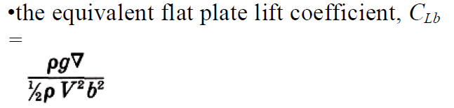
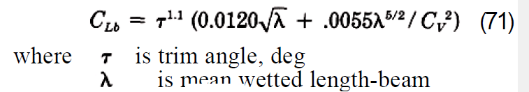
- Step 3 – Calculate the equivalent flat plate lift coefficient: This is calculated by using the formula:
- Step 4 – Calculate the lift coefficient for a finite deadrise: Depending on the deadrise angle β, the lift coefficient for a finite deadrise is calculated from the flat plate lift coefficient by using the following formula:
![]()
- Step 5 – Calculate the p/b ratio, where p = longitudinal center of gravity (LCG) of the vessel (see below)
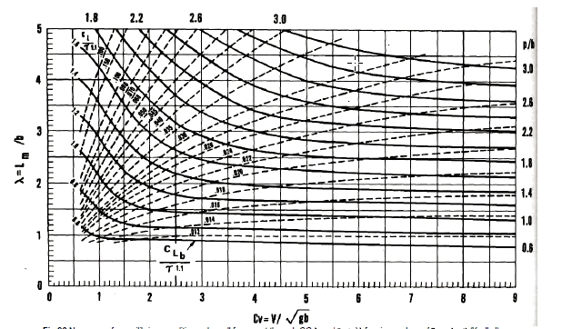
- Step 6 – Calculate the mean wetted length-beam ratio: This is the ratio λ = Lm/b, which is obtained from the Koelbel’s curves.
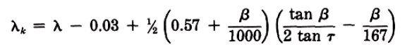
- Step 7 – Calculate the trim of the vessel in equilibrium: This is calculated by using the Savitsky formula:
Here λ is the ratio of the mean wetted length to the beam of the planing area, i.e., Lm/b, obtained in Step 6
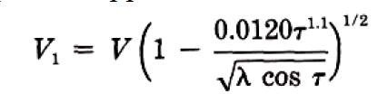
- Step 7 – Calculate the keel-wetted length ratio: This is calculated by using the formula:
- Step 8 – Check if the vessel is fully planing: If λk <= LWL/b, then it is fully planing, i.e., the bow is clear of water, else it is not. If it is fully, planing, then the method is valid, else this method is not applicable for vessels not fully planing
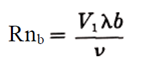
- Step 9 – Use the formula to calculate resistance:

W is displacement. Here, CFO is calculated from ITTC Line, using the following formula
CFO = 0.075/(log10Rn -2)2
Do check our our product Planing Vessel Resistance Calculator
References
- https://en.wikipedia.org/wiki/Planing_(boat)
- Principles of Naval Architecture Second Revision, Volume II Resistance, Propulsion and Vibration
Disclaimer: This post is not meant to be authoritative writing on the topic presented. thenavalarch bears no responsibility for the accuracy of this article, or for any incidents/losses arising due to the use of the information in this article in any operation. It is recommended to seek professional advice before executing any activity which draws on information mentioned in this post. All the figures, drawings, and pictures are property of thenavalarch except where indicated, and may not be copied or distributed without permission.
FLOATING WIND TURBINES -TRANSPORTATION AND INSTALLATION ENGINEERING
By Alan Crowle, BSc, MSc, CEng, CMarEng, FRINA, FMAREST, FSCMS Masters by Researcher, University of Exeter, College of Engineering, Mathematics and Physical Sciences, Renewable Energy Group Summary Floating offshore wind turbines are an emerging source of marine...
Preparation for Dry-docking of an oil tanker: A Chief Engineer’s approach
Introduction Dry-docking of a vessel is required at every 5 yearly intervals to carry out inspection of hull, propeller and other components which are normally submersed in water all the time. This is a requirement by ship’s classification societies. However, some...
Using simple tools for efficient Passage Planning for seagoing vessels
Introduction Planning a vessel’s voyage is a critical detailed exercise, and the main goal is to ensure safe and efficient passage between two ports. The Master has the responsibility for the vessel voyage planning, but very often he delegates the actual voyage...
Designing a closed chock as per IACS rules
Introduction Chocks are used universally for mooring and towing operations on ships. For towing operations, Chocks are used for guiding the towing rope from the winch through the outer shell of the vessel to the tug. For mooring operations, the chock is used to...
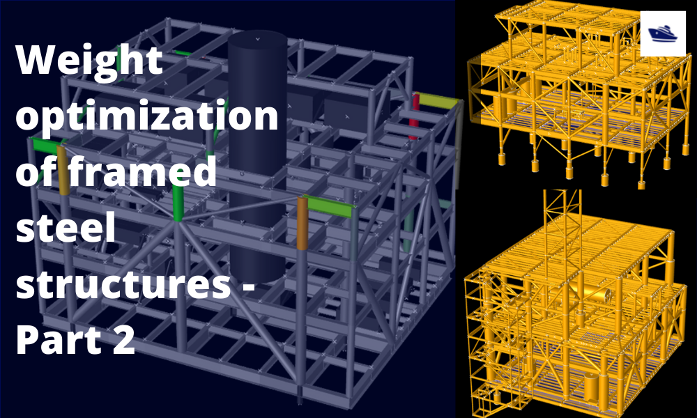
The Optim22 method of hull optimization – Part 2
This is a follow-up article to the previous article on Framed Structures Optimization. 1.1 Abstract A previous article introduced the Optim22 method. This one adds additional background information plus 3 more case studies to...
The Optim22 Method of Weight Optimization of Framed Steel Structures
1 Abstract A semi-automated structural weight optimization system is presented for framed structures of post and beam construction which is based on basic structural member design principles. The approach is to adjust member properties in a manner that...

Combating rising seas with floating structures
Introduction Rising sea level is an existential threat for many coastal cities. The sea is rising subtly but relentlessly at an exponential rate. Many predictions of how high and how fast it will rise in the next 50 years have proved to be understated. According to...
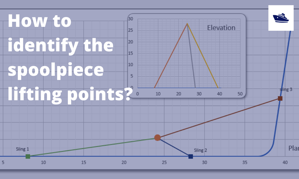
How to identify the spoolpiece lifting points?
In the offshore construction industry, the connection between the newly installed pipeline and the riser is accomplished via a series of ‘spoolpieces’ (or spools). The spool is fabricated by welding pipe joints to form an L-shaped, Z-shaped, or possibly a straight...
The importance of clear decision support before marine operations
Our oceans are interspersed with human activities: be it fishing, marine transportation, or offshore operations. These operations usually involve assets worth multiple million dollars, be it the produce or the equipment or in most cases, the human life. Produce from...
Sea Pressure Loads Calculation based on DNV Rules
Introduction Sea pressure loads are an important factor in the structural design of a vessel. What is sea pressure load? As the term suggests, it is the external pressure on the vessel due to the surrounding sea. What kind of pressure it is, and how to...
Please check out TheNavalArch’s product for planing vessel resistance estimation:

Hi Prem,
I will read this with much of interest.
Brgds
Costas