Introduction
Pipes (or linepipes or joints) are used for multiple purposes and locations in the maritime/offshore industry. Onshore and offshore pipelines are used for transportation of fluids on land, over and underwater.
Pipes are fabricated in an onshore facility and they may be transported using trucks, ships, or barges to the location where they are to be installed. They may also need to be stored in the yard before they can be loaded on to trucks/ships.
How do we store pipes? Naturally, the easiest way is to stack them layer over layer, as shown in
Fig 1 below.
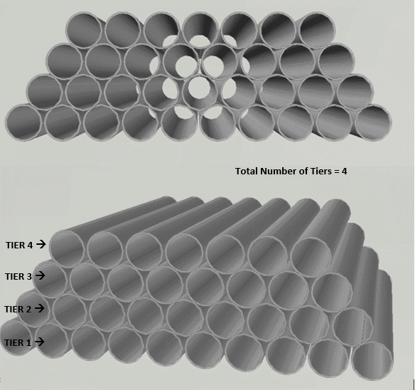
Figure 1: Tiers and stacking of pipes
Nested Diameter, Pipe Yield Stress and Stacking height limit
Pipes can be stacked one above another forming different tiers or ‘stacks’. The pipes of the second tier (the one just above the bottom tier) will sit in the grooves created in the bottom tier. Similarly, the third-tier pipes will sit in the grooves of the second tier and so on. If we continue like this, a trapezium-shaped stacking will be created, as shown in Figure 1 above.
Nested OD
This type of stacking is called ‘nested’ stacking (pipes sitting in grooves). With the pipes sitting in the grooves, the total height of a stack of pipes is less than the number of stacks times the diameter. This gives rise to the term ‘Nested Diameter’. Nested Outer Diameter (Nested OD) is the total height of the stack divided by the number of stacks. This is lesser than a pipe’s outer diameter.
Nested Diameter (Nested OD) = Total Height of Pipe Stack / Number of stacks
Below we will derive a simple formula for Nested OD.
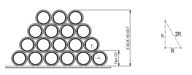
In the above figure, R is radius of pipe = Pipe Outer Diameter (OD)/2.
h = vertical distance between two tiers = √3/2 x Pipe OD
If the number of tiers is n, then
Stack Height, H = R (for bottom tier lower half) + (n-1) x h + R (for top tier upper half)
H = pipe OD + (n-1) x √3/2 x pipe OD
Nested OD = H/n
Stacking Height Limit
This naturally raises a question: how high can we keep stacking pipes safely? As we keep stacking, we realize that the bottom tier of the pipe takes an increasingly higher weight. The stacking height is determined by the maximum number of stacks that we can add before the bottom tier yields. How do we measure this yielding?
- For bare pipes, the yield limit is the yield stress of steel of pipe
- For concrete pipes, either the concrete or the steel may yield. The first one to yield governs the yield limit
- For pipes with anti-corrosion coating, the coating may also yield, but it is usually not governing in comparison to steel and concrete yielding.
Let’s talk a bit more in detail about calculating the stacking limit by taking the case of bare pipes. For the bottom tier of pipes, the following loads are acting –
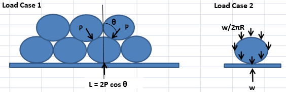
- Load Case 1 – Load due to pipes above
- Load Case 2 – Self-weight
These two are depicted below:
How do we calculate the value of L, the load on the bottom tier?
We can see that L is the load due to the weight of the tiers above. Hence, if the total number of tiers is ‘n’, then the load of the tiers above is L = (n -1) x w, where w is the weight per unit length of the pipe. This load comes onto the bottom pipe from the two pipes above at angle 30 degrees to the vertical.
Thus L = 2P cos 30. This gives P = L/ (2 cos30) = (n-1) x w/ (2 cos30)
From Roark’s formula, the maximum moment which the pipes are subjected to due to the first load case is M1 = 0.5106 PR (See Table 9.2, Case 5, KMC = 0.5106). R is the pipe radius
Thus, the moment from the first load case,
M1 = 0.2948 (n-1) wR
The second load on the pipe is the self-weight, which gives as per Roark’s formula (Table 9.2, Case 15),
M2 = 1.5{w/(2πR)}R2 = 0.2387wR
Combining the two moments, we get
Total moment on the bottom pipe, M = M1 + M2 = (0.2948n – 0.0561)wR
The bending stress is calculated as,
Bending Stress on pipe = Bending Moment/ Section modulus of pipe for transverse bending.
Section modulus for transverse bending = t2/6, where ‘t’ is the pipe thickness
This gives the bending stress as
σBEND = M/Z = (n – 0.1903)wR/(0.5654t2)
If the allowable bending stress is σALLOW, then σBEND has to be less than σALLOW. From this, we get
n < 0.5654 σallowt2/wR + 0.1903
From the above in-equality, we can see that the number of tiers has to be less than 0.5654 σallowt2/wR + 0.1903.
Once we know the maximum number of tiers that can be stacked, we can use the formulas specified before to calculate the stacking height and nested OD
H = pipe OD + (n-1) x √3/2 x pipe OD
Nested OD = H/n
Thus, by using simple principles of force resolution and basic stress calculations, we can find out how many tiers of a particular pipe type can be stacked up, and to what height.
For subsea pipelay operations, multiple pipe types may be present with varying properties. The stacking height of each of them can be calculated using this principle.
Disclaimer: This post is not meant to be authoritative writing on the topic presented. thenavalarch bears no responsibility for the accuracy of this article, or for any incidents/losses arising due to the use of the information in this article in any operation. It is recommended to seek professional advice before executing any activity which draws on information mentioned in this post. All the figures, drawings, and pictures are property of thenavalarch except where indicated, and may not be copied or distributed without permission.
FLOATING WIND TURBINES -TRANSPORTATION AND INSTALLATION ENGINEERING
By Alan Crowle, BSc, MSc, CEng, CMarEng, FRINA, FMAREST, FSCMS Masters by Researcher, University of Exeter, College of Engineering, Mathematics and Physical Sciences, Renewable Energy Group Summary Floating offshore wind turbines are an emerging source of marine...
Preparation for Dry-docking of an oil tanker: A Chief Engineer’s approach
Introduction Dry-docking of a vessel is required at every 5 yearly intervals to carry out inspection of hull, propeller and other components which are normally submersed in water all the time. This is a requirement by ship’s classification societies. However, some...
Using simple tools for efficient Passage Planning for seagoing vessels
Introduction Planning a vessel’s voyage is a critical detailed exercise, and the main goal is to ensure safe and efficient passage between two ports. The Master has the responsibility for the vessel voyage planning, but very often he delegates the actual voyage...
Designing a closed chock as per IACS rules
Introduction Chocks are used universally for mooring and towing operations on ships. For towing operations, Chocks are used for guiding the towing rope from the winch through the outer shell of the vessel to the tug. For mooring operations, the chock is used to...
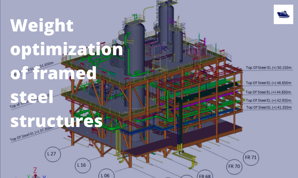
The Optim22 method of hull optimization – Part 2
This is a follow-up article to the previous article on Framed Structures Optimization. 1.1 Abstract A previous article introduced the Optim22 method. This one adds additional background information plus 3 more case studies to...
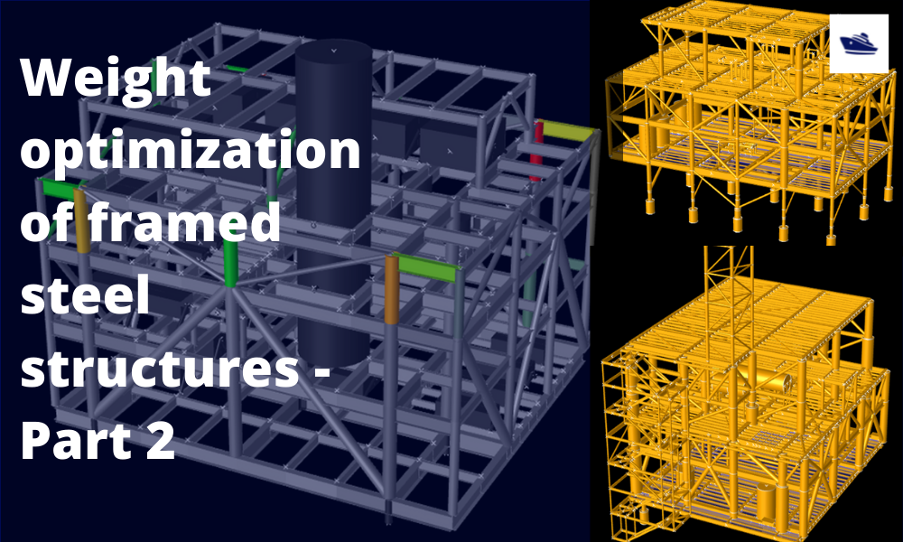
The Optim22 Method of Weight Optimization of Framed Steel Structures
1 Abstract A semi-automated structural weight optimization system is presented for framed structures of post and beam construction which is based on basic structural member design principles. The approach is to adjust member properties in a manner that...

Combating rising seas with floating structures
Introduction Rising sea level is an existential threat for many coastal cities. The sea is rising subtly but relentlessly at an exponential rate. Many predictions of how high and how fast it will rise in the next 50 years have proved to be understated. According to...
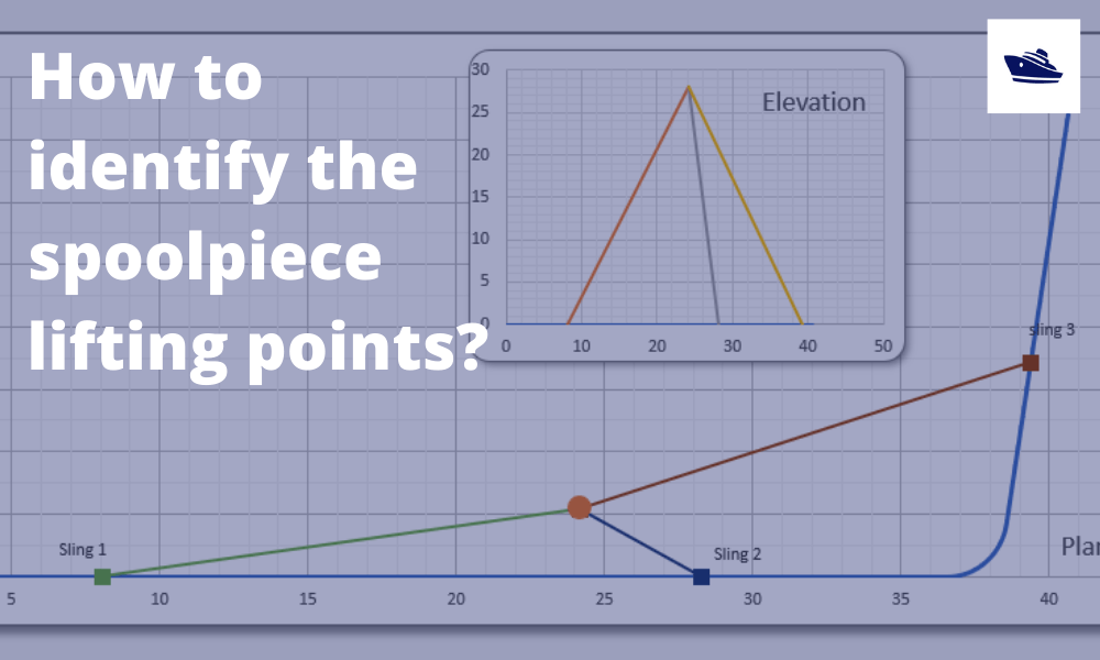
How to identify the spoolpiece lifting points?
In the offshore construction industry, the connection between the newly installed pipeline and the riser is accomplished via a series of ‘spoolpieces’ (or spools). The spool is fabricated by welding pipe joints to form an L-shaped, Z-shaped, or possibly a straight...
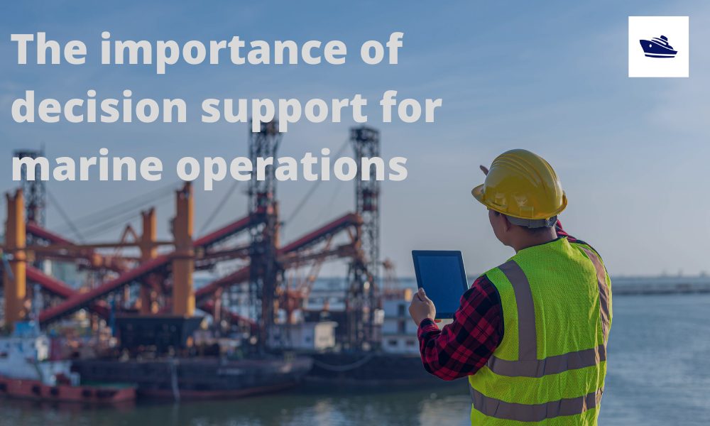
The importance of clear decision support before marine operations
Our oceans are interspersed with human activities: be it fishing, marine transportation, or offshore operations. These operations usually involve assets worth multiple million dollars, be it the produce or the equipment or in most cases, the human life. Produce from...
Sea Pressure Loads Calculation based on DNV Rules
Introduction Sea pressure loads are an important factor in the structural design of a vessel. What is sea pressure load? As the term suggests, it is the external pressure on the vessel due to the surrounding sea. What kind of pressure it is, and how to...

i need a help with the plan on stacking of storm water pipes
Hi Rose
Thanks for the inquiry. Sent you an email
Hi,
May I know the height limit if:
OD = 90cm
length = 5m
Weight = 400kgs
Thank you.
I need a help with with the plan on stacking of Casing different Sizes.
Hi Sain
Can you write with more details to us at info@thenavalarch.com? Thanks
Steel pipe loading on ship calculation
Looking for recommended calculations for pipe stacking in bridge configuration. Thanks
What is formula of the Lashing Calculate ondeck load cargo
Hi Yasar, you can do it based on IMO CSS. If you need help in doing it, feel free to write to us at info@thenavalarch.com
what is the maximum height/tier for stacking of pipes of various diameter/sizes
Stacking hight for 400mm hdpe 12m lenght