Introduction
A keyless propeller, as the name implies, requires no key for fastening the propeller on the cone of the propeller shaft. How is the torque then transferred to the propeller? The torque is transferred by the friction between the propeller and the propeller shaft.
In this article, we’ll see what important parameters govern the design of a keyless propeller, and how these can be calculated.
These are based on ABS Rules for Building and Classing Steel Vessels 2019, Part 4 Vessel systems and machinery, Section 3 Propellers. Class rules require a minimum factor of safety against the slip of 2.8, which can be used to calculate the maximum pull-up load. This load also depends on several other parameters like the type of propulsion, diameters of boss and hub, rated thrust, etc. that have been discussed below.
Design Parameters
The following design parameters are important for the keyless propeller design:
- Minimum required mating surface pressure
- Minimum pull-up length
- Pull-up Load
- Dry-fitting
- Wet-fitting
- Contact surface pressure
- Hoop stress
- Equivalent stress
Parameters like mating surface pressure and pull-up length also depend on the temperature of operation.
Design Criteria
The design criteria as per ABS rules are as follows:
- The factor of safety against the slip of the propeller hub on the tail shaft taper at 35°C (95°F) is to be at least 2.8 under the action of maximum continuous ahead rated torque plus torque due to torsional vibrations.
- The maximum equivalent uniaxial stress (von Mises-Hencky criteria) in the hub at 0°C (32°F) is not to exceed 70% of the minimum specified yield stress or 0.2% proof stress of the propeller material.
- The calculations submitted must cover the following parameters:
- Theoretical contact surface area
- The maximum permissible pull-up length at 0°C (32°F) as limited by the maximum permissible uniaxial stress specified above
- The minimum pull-up length and contact pressure at 35°C (95°F) to attain a safety factor against slip of 2.8
- The proposed pull-up length and contact pressure at the fitting temperature
- The rated propeller ahead thrust
Inputs
The calculations will require multiple inputs related to the propeller’s geometry and material, along with the vessel’s parameters like speed.
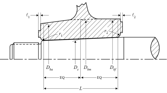
The inputs all follow the rule requirements by ABS, and are listed below. The diagram below also depicts some of the inputs.
- Contact surface area between propeller hub and shaft taper (A)
- Coefficient of friction between mating surfaces (µ)
- Half taper of shaft (θ)
- Factor of safety against slippage at 35°C (S)
- Coefficient for type of propulsion drive (c)
- Outer diameter of hub corresponding to Ds (Dbm)
- Outer diameter of hub corresponding to the forward point of contact (Dbf)
- Outer diameter of hub corresponding to the aft point of contact (Dba)
- Mean outer diameter of hub corresponding to Ds (Db)
- Diameter of shaft at mid-point of the taper in axial direction (Ds)
- Mean propeller pitch (P)
- Rated propeller thrust
- Calculated based on Power at rated speed (H), Vessel speed at rated power (v), and Rpm at rated speed (R), OR
- from designer (T-User)
- Modulus of elasticity of hub material (Eb)
- Poisson’s ratio of hub material (νb)
- Coefficient of linear expansion of propeller hub material (αb)
- Modulus of elasticity of shaft material (Es)
- Poisson’s ratio of shaft material (νs)
- Coefficient of linear expansion of shaft material (αs)
- Yield stress or 0.2% proof stress of propeller material (σy)
- Reference temperature as per rule (tref)
- Contact length (L)
Calculations
The formulations for the various parameters are shown below:
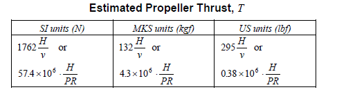
- Rated propeller thrust – if the designer has this value, then the designer’s value is used, else the value from rules can be used
- Rated Torque – Q is the rated torque which is an input corresponding to H & R, however, it can be estimated from the formula below
![]()
- Shear force at the propeller-shaft interface

- Pull-up length
The minimum pull-up length is taken at 35 degrees C, and is given by

The minimum pull-up length at any other temperature (less than 35 degrees) is given by

- Minimum mating surface pressure at 35 degrees C is given by
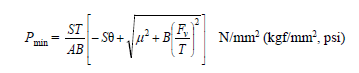
The minimum mating surface pressure varies with temperature, and at another temperature less than 35 degrees C, it is given by

Here δmin and δt are the pull-up lengths at 35 deg and at temperature ‘t’ respectively.
- Pull-up load
The pull-up load can be calculated using the formula below:
Wt (pull-up load) = A x Pt (μ + θ), where
μ = coefficient of friction between mating surfaces. For wet fitting, the friction is considerably lower than dry fitting
θ = Half taper of shaft
- Stresses: The hoop stress and equivalent stress can be given by:
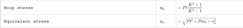
where K is the ratio of Db and Ds
That brings us to the end of this article. TheNavalArch also has its own product which simplifies the above calculations for the user. Please do check it out
References
- ABS Rules for Building and Classing Steel Vessels 2019 , Part 4 Vessel systems and machinery, Section 3 Propellers
- https://trid.trb.org/view/63325
Disclaimer: This post is not meant to be authoritative writing on the topic presented. thenavalarch bears no responsibility for the accuracy of this article, or for any incidents/losses arising due to the use of the information in this article in any operation. It is recommended to seek professional advice before executing any activity which draws on information mentioned in this post. All the figures, drawings, and pictures are property of thenavalarch except where indicated, and may not be copied or distributed without permission.
https://thenavalarch.com/software/maritime-industry-thenavalarch/ship-design/resistance-propulsion/keyless-propeller-fitting-calculations/
FLOATING WIND TURBINES -TRANSPORTATION AND INSTALLATION ENGINEERING
By Alan Crowle, BSc, MSc, CEng, CMarEng, FRINA, FMAREST, FSCMS Masters by Researcher, University of Exeter, College of Engineering, Mathematics and Physical Sciences, Renewable Energy Group Summary Floating offshore wind turbines are an emerging source of marine...
Preparation for Dry-docking of an oil tanker: A Chief Engineer’s approach
Introduction Dry-docking of a vessel is required at every 5 yearly intervals to carry out inspection of hull, propeller and other components which are normally submersed in water all the time. This is a requirement by ship’s classification societies. However, some...

Using simple tools for efficient Passage Planning for seagoing vessels
Introduction Planning a vessel’s voyage is a critical detailed exercise, and the main goal is to ensure safe and efficient passage between two ports. The Master has the responsibility for the vessel voyage planning, but very often he delegates the actual voyage...
Designing a closed chock as per IACS rules
Introduction Chocks are used universally for mooring and towing operations on ships. For towing operations, Chocks are used for guiding the towing rope from the winch through the outer shell of the vessel to the tug. For mooring operations, the chock is used to...
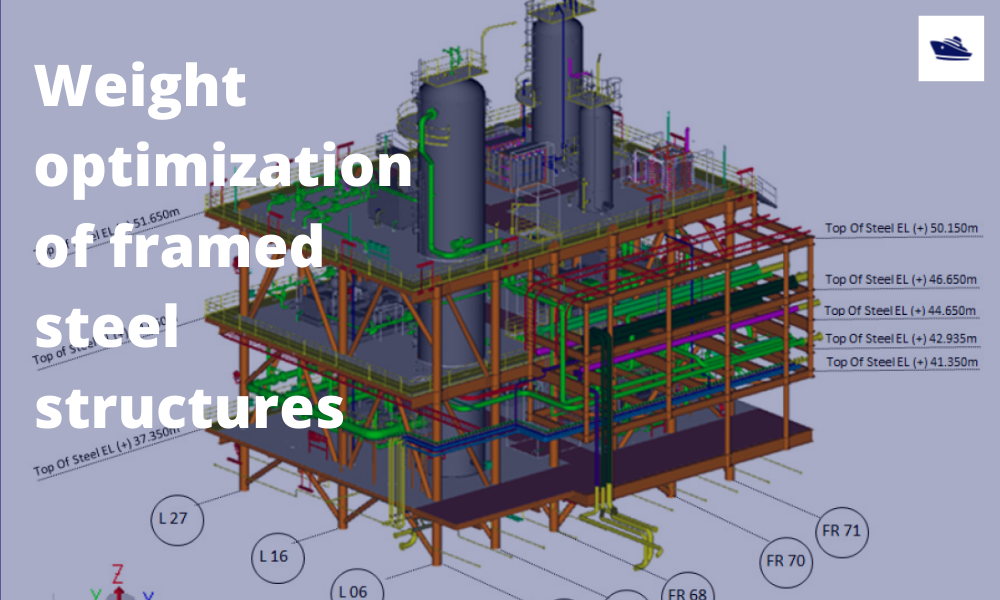
The Optim22 method of hull optimization – Part 2
This is a follow-up article to the previous article on Framed Structures Optimization. 1.1 Abstract A previous article introduced the Optim22 method. This one adds additional background information plus 3 more case studies to...
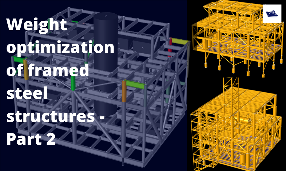
The Optim22 Method of Weight Optimization of Framed Steel Structures
1 Abstract A semi-automated structural weight optimization system is presented for framed structures of post and beam construction which is based on basic structural member design principles. The approach is to adjust member properties in a manner that...

Combating rising seas with floating structures
Introduction Rising sea level is an existential threat for many coastal cities. The sea is rising subtly but relentlessly at an exponential rate. Many predictions of how high and how fast it will rise in the next 50 years have proved to be understated. According to...
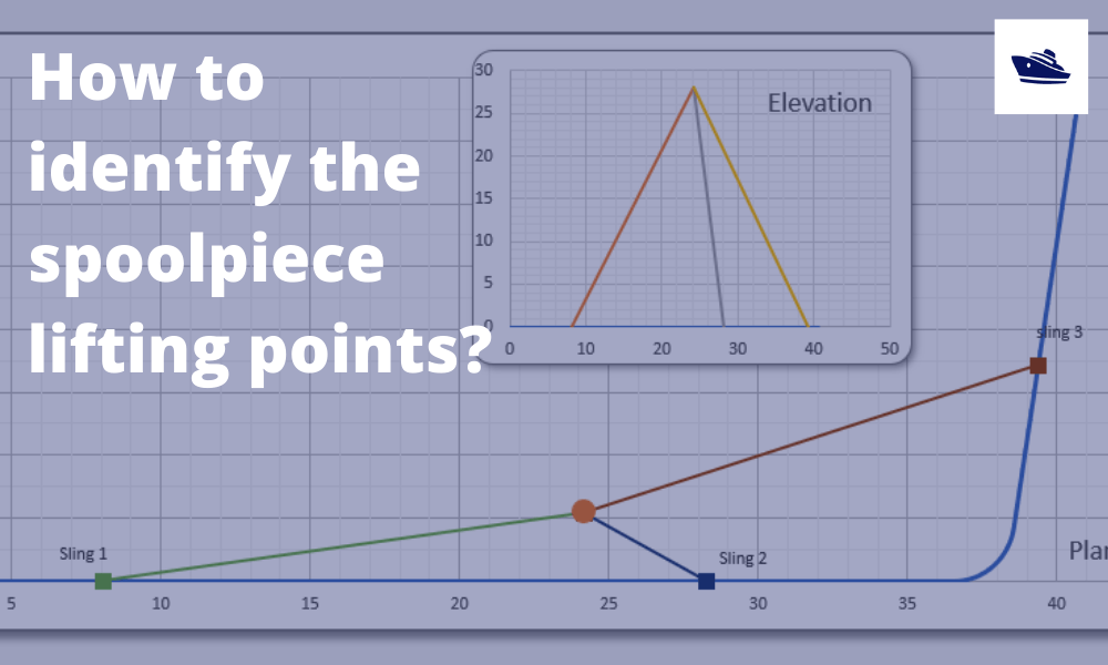
How to identify the spoolpiece lifting points?
In the offshore construction industry, the connection between the newly installed pipeline and the riser is accomplished via a series of ‘spoolpieces’ (or spools). The spool is fabricated by welding pipe joints to form an L-shaped, Z-shaped, or possibly a straight...
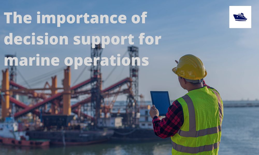
The importance of clear decision support before marine operations
Our oceans are interspersed with human activities: be it fishing, marine transportation, or offshore operations. These operations usually involve assets worth multiple million dollars, be it the produce or the equipment or in most cases, the human life. Produce from...
Sea Pressure Loads Calculation based on DNV Rules
Introduction Sea pressure loads are an important factor in the structural design of a vessel. What is sea pressure load? As the term suggests, it is the external pressure on the vessel due to the surrounding sea. What kind of pressure it is, and how to...
