Introduction
Capstans are frequently deployed mooring equipment used on all types of vessels. Capstans are berthing/mooring equipment used to multiply the pulling force on mooring ropes.
Traditionally, Capstans were operated manually but in modern ships, they are operated wither electro-hydraulically or electromechanically.
When Capstans are used in mooring ships, they have to be sufficient in size and number to overcome the forces which the ship experiences in the lateral direction due to environmental forces of wind and current. How do we know what size capstans will be sufficient? We’ll take a detailed look at in this article.
This article is based on DDS-582-1 Calculations for Mooring Systems, Department of the Navy, Naval Sea Systems Command, Washington DC, 20362-5101.
The Concept
When berthing a vessel, a number of capstans on the vessel may be utilized simultaneously. How do we determine if the capstan size is sufficient?
Thinking in basic terms, the berthing operation of the vessel will impose some forces on the vessel, which are transferred through the berthing lines to the capstans. What forces are these?
At the berth, the two major forces are the wind and current forces that the vessel experiences. Also, since the vessel is mostly berthed sideways, these forces must be calculated on the side of the vessel (not on the front).
The wind and current forces are characterized by the wind and current speed at the berth.
Thus, a simple approach to determine the capstan design will be:
- Calculate the lateral berthing forces (wind and current) on the vessel
- Divide the total lateral berthing force by the number of capstans to get the force per capstan. This will give the required line pull of the capstan
- The capstan power is obtained by dividing the required line pull times the warping speed by the capstan’s efficiency.
Environmental Forces
The first step is calculating the environmental forces on the vessel. Generally, at berth, wind, and current are the most significant forces, while wave forces can be generally ignored.
When calculating the wind and current forces, the standard physics formula of Force = Pressure x Area shall be used. In the method by DDS-582 (Ref 3), wave forces have not been considered for doing the calculation.
For wind force, the formula is Fwind = 1/2 x Cwind x ρwind x Vwind2 x Awind, where Cwind is the coefficient of wind force, ρwind is the density of air, Vwind is the wind speed, and Awind is the total area of ship and cargo which is exposed to the wind from beam direction (the above-water area)
Similarly, for current force, the formula is Fcurrent = 1/2 x Ccurrent x ρwater x Vcurrent2 x Aunderwater, where Ccurrent is the coefficient of current force, ρwater is the density of water, Vcurrent is the current speed, and Aunderwater is the total underwater area of ship which is exposed to the current from beam direction.
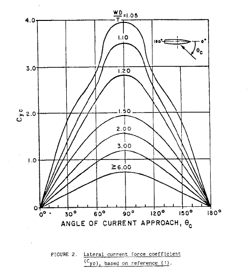
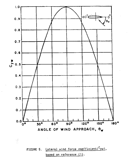
The critical items in the calculations for Wind and Current forces are the force coefficients for wind and current.
These coefficients can be obtained from the coefficient plots provided in DDS-582, and some plots are presented below:
Lateral Current Coefficient (DDS-582)
Lateral Wind Coefficient (DDS-582)
We can see that the lateral current force is dependent on an additional factor: the underkeel clearance which is measured as Water Depth to Draft ratio (WD/T).
At the end of this exercise, we’ll have the following with us:
- Wind Force – transverse
- Current force – transverse
Next exercise is using these forces and calculate the capstan line pull using the environmental forces.
Capstan Design
Once we have the wind and current lateral forces, we add them up together to give the total lateral force on the vessel.
Total Lateral Force, FY = FYW + FYC, where
FY = total lateral force on the vessel
FYW = lateral wind force on the vessel
FYC = lateral current force on the vessel
If the number of capstans is ‘n’, then the line pull per capstan is given by:
PCP = FY/n
Once the line pull is available, the minimum required Capstan power is determined as follows:
PCAPSTAN = PCP x VCP/ηCAPSTAN
Here,
PCAPSTAN = Required minimum capstan power
VCP = Capstan’s warping line speed
ηCP = Capstan’s efficiency
The Capstan’s efficiency has the following components:
- Capstan Head Efficiency
- Overall bearing and gear efficiency
- For electro-hydraulic capstans additionally – Efficiency of Hydraulic Pump and Motor
From the above process, we can obtain the minimum required Capstan’s power using which we can select the right capstan, or we can evaluate the suitability of an existing capstan for berthing.
TheNavalArch has its own app for selecting the right capstan. Do check it out from the link below.
References
- https://en.wikipedia.org/wiki/Capstan_(nautical)
- https://www.brighthubengineering.com/seafaring/51281-what-is-a-capstan-on-a-ship/
- DDS-582-1 Calculations for Mooring Systems, Department of the Navy, Naval Sea Systems Command, Washington DC, 20362-5101
TheNavalArch Interview Series: Capt Robin Perera
TheNavalArch's Interview Series is an endeavor to get insights from the best engineering and business brains in the industry and present them to its users for the larger benefit of the maritime community. Leaders share their experiences and ideas that readers can gain...
TheNavalArch Interview Series: Mr Victor Valera
TheNavalArch's Interview Series is an endeavor to get insights from the best engineering and business brains in the industry and present them to its users for the larger benefit of the maritime community. Leaders share their experiences and ideas that readers can gain...
TheNavalArch Interview Series: Mr Steven Lu
Mr. Steven LuManaging DirectorEpoch Offshore Engineering (Shanghai) Co., Ltd. TheNavalArch's Interview Series is an endeavor to get insights from the best engineering and business brains in the industry, and present them to its users for the larger benefit of the...
TRANSPORT VESSELS FOR FLOATING WIND
By Alan Crowle, BSc, MSc, CEng, CMarEng, FRINA, FMAREST, FSCMS Masters by Researcher, University of Exeter, College of Engineering, Mathematics and Physical Sciences, Renewable Energy Group SUMMARY Floating wind turbine construction is a large logistical exercise. The...
TheNavalArch Interview Series: Mr. Balakrishna Menon
Mr. Balakrishna MenonEngineering Director Mooreast (Asia) Pte Ltd TheNavalArch's Interview Series is an endeavor to get insights from the best engineering and business brains in the industry, and present them to its users for the larger...
Floating Rice Fields, the quest for solutions to combat drought floods and rising sea levels
by Lim Soon Heng, BE, PE, FSSS, FIMarEST Founder President, Society of FLOATING SOLUTIONS (Singapore) Abstract Amazing as it seems, there is a case for growing rice on floating platforms in the sea. The capital expenditure to develop this is offset by the opportunity...

CAPSIZE OF LIFTBOAT IN TRANSIT
This paper was originally presented in the 27th Offshore Symposium, February 22nd, 2022, Houston, Texas Texas Section of the Society of Naval Architects and Marine Engineers It has been reproduced here for the readers of TheNavalarch INTRODUCTION In 1989 a Class 105...
Preparation for Dry-docking of an oil tanker: A Chief Engineer’s approach
Introduction Dry-docking of a vessel is required at every 5 yearly intervals to carry out inspection of hull, propeller and other components which are normally submersed in water all the time. This is a requirement by ship’s classification societies. However, some...
Using simple tools for efficient Passage Planning for seagoing vessels
Introduction Planning a vessel’s voyage is a critical detailed exercise, and the main goal is to ensure safe and efficient passage between two ports. The Master has the responsibility for the vessel voyage planning, but very often he delegates the actual voyage...
Designing a closed chock as per IACS rules
Introduction Chocks are used universally for mooring and towing operations on ships. For towing operations, Chocks are used for guiding the towing rope from the winch through the outer shell of the vessel to the tug. For mooring operations, the chock is used to...

Work as a Project Engineer at Colombo Dockyard PLC for New Building Projects
Comment *Looks like an interesting article