By Tamal Mukherjee,
This is the Part 1 of a two part article on the Bulbous Bow. Part 2 can be accessed here
*This article originally appeared in May 2019 edition of Marine Engineers Review (India), the Journal of Institute of Marine Engineers India. It is being reproduced here for the readers of TheNavalArch’s blog.
Introduction
A bulbous bow is an extension of the hull just below the load waterline. The basic purpose is to create a low-pressure zone to reduce or eliminate the bow wave and reduce the resulting drag. Today the bulbous bow is a normal part of modern seagoing cargo ships. Comparative model experiments show that a ship fitted with a bulbous bow can require far less propulsive power and have considerably better resistance characteristics than the same ship without a bulbous bow.
Who invented the bow
The bulbous bow was discovered rather than invented. Before 1900, towing tests with warships in the USA established that the ram stem projecting below the water decreased resistance. A torpedo boat model showed that an underwater torpedo discharge pipe ending in the forward stern also reduced the resistance. A bulbous bow was first used in 1912 by the US navy. It was not until 1929 that the first civil ships were fitted with them. These were the passenger ships Bremen and Europa belonging to the Norddeutscher Lloyd of Bremen. A more widespread application in cargo shipping did not happen until the 1950s. The first bulb for tankers was installed in 1957.
Principle of the bow
The principle of the bulbous bow is that it is sized, shaped and positioned so as to create a wave system at the bow which partially cancels out the ship’s own bow wave system, so reducing wave-making resistance. This can only be done over a limited speed range and at the expense of resistance at other speeds. Many merchant ships operate at a steady speed for much of their lives so the bulb can be designed for that speed. It was originally applied to moderate to high-speed ships but has also been found to be beneficial in relatively slow ships such as tankers and bulk carriers and these ships now often have bulbous bows. The effectiveness of the bulb in the slower ships, where wave-making resistance is only a small percentage of the total, suggests the bulb reduces frictional resistance as well. This is thought to be due to the change in flow velocities that it creates over the hull. Sometimes the bulb is sited well forward and it can extend beyond the fore perpendicular.
In marine hydrodynamic applications, the Froude number is a dimensionless number based on the speed length ratio. It is usually referenced with the notation Fn and is defined as:
Fn = Vs/sqrt(gL)
Where Vs is the relative flow velocity between the sea and ship, g is the acceleration due to gravity, sqrt refers to ‘square root of’, and L is the length of the ship at the water-line level. It is an important parameter with respect to the ship’s drag, or resistance, especially in terms of wave-making resistance.
A normal bow is cheaper to manufacture and a bulbous bow should only be fitted if doing so will reduce the resistance and thereby either increase the speed or reduce the power required, and with it the fuel consumption. It is seen that there is a range of Froude numbers(Fn) and block coefficients(Cb) at which such improvement is likely to be obtained when operating at the load draft.
It can be seen that bulbous bows are advantageous for fast ships with Cb, values less than 0.625 and Fn greater than about 0.26; and are advantageous for Cb values between 0.725 and 0.825 but probably not for Cb values over 0.825. It must be emphasized that this analysis refers only to the Load draft condition. It is generally accepted, however, that bulbous bows can offer their greatest advantage in the ballast condition, particularly on full lined ships with block coefficients in excess of 0.75. In the past, when tankers and bulk carriers making lengthy ballast voyages used their full power on this leg, the gain in ballast speed was a clinching argument for fitting a bulbous bow. Today fuel economy often keeps ballast speeds down to, or lower than, the loaded service speed. and the argument for a bulbous bow is reduced. It is worth emphasizing that the overall economy may require a balance between designing for optimum performance fully loaded and in the ballast condition.
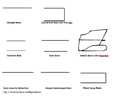
A bulbous bow will generally help in reducing pitching, but on the other hand, it is more likely to cause slamming. Bulbous bows come in a variety of shapes and sizes, as shown in Fig. 1. One main division is that between a fully-faired bulb and one in which there is a sharp knuckle line between the bulb and a normal bow configuration. Claims have been made for the advantages of each type, but the “added” bulb is generally simpler to manufacture and seems, on full lined ships, to give at least as good results as the faired bulb. The next division is between bulbs which project as rams significantly forward of the fore perpendicular and those with little or no such projection. Ram bows also vary in the vertical positioning of the forward projection. which in some designs commence near the waterline and in others are well submerged. One of the principal criteria applied to the design of a bulbous bow is the relationship that its sectional area at the fore perpendicular bears to the mid-ship section area.
A bulbous bow works best under certain conditions and good design gives efficiency gains throughout the range of these factors. At low speeds, a bulbous bow will trap water above the bulb without forming a low-pressure zone to cancel the bow wave. This will actually cause increased drag and lead to loss of efficiency. It is often suggested that the usefulness of a bulb is limited in the interval
0.238 <= Fn <= 0 563. Fn being the Froude Number.
Generally, at low speeds, the effect of the bulb is negative. With increasing Froude Number, its effect becomes positive and increases up to a maximum value.
The bulbous bow offers several advantages apart from reducing bow wave, it works as a robust “bumper” in the event of a collision. It allows the installation of the bow thrusters at a foremost position, making it more efficient. It provides for a Larger reserve of flotation or a larger ballast capacity forward and also reduces pitching of the vessel.
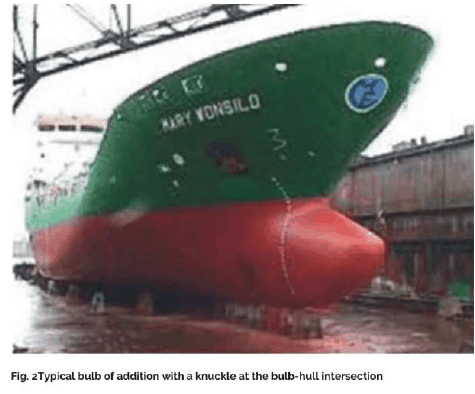
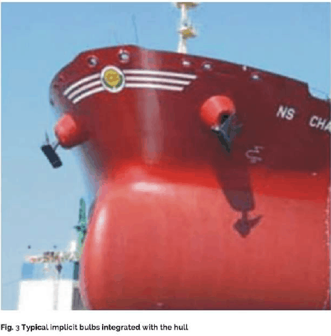
The bulb shapes can be classified as Addition Bulbs and Implicit Bulbs. The Addition bulbs look as if added to the hull as a separate entity. Here the bulb shape is completely independent of the hull shape. Typically there is a knuckle resulting from the intersection of the bulb and the hull as shown in Fig. 2. In the case of Implicit bulbs, they are a continuation of the hull and therefore no knuckles are required as shown in Fig. 3
The bulbs generally have heavily curved surfaces making them expensive for production. Some compromise on the hydrodynamic efficiency of the bulbs could result in a reduction in their production costs. Following guidelines may be considered while designing a bulb to make it less cost-intensive:
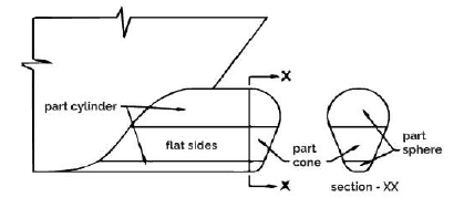
- Maximize use of single curvature
- Use conic sections.
- Decrease the curvature of the freeform curved plates, decomposing them into smaller ones.
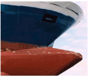
Examples of simplified bulb form are shown in Figs. 4 and 5
Fig 4 – A simplified bulb form
Fig 5 – Schematic of a simplified bulb form
Bulbous bow form characteristics
Bulbous bows are defined using the following form characteristics:
- The shape of the section.
- Side-view.
- Length of projection beyond perpendicular.
- Position of the axis.
- Area ratio,
- Transition to hull
In Part 2 of this article, we’ll go deeper into the above characteristics. We’ll also see the effects which a bulb has on the entire life cycle of a ship – from design to constructions to operation and seakeeping. Plus, we’ll dive into the practical criteria which we should take into account for deciding whether a bulbous bow is feasible for a vessel.
Access PART 2 of this article below:
https://thenavalarch.com/the-bulbous-bow-types-characteristics-and-effects/
About the Author
Tamal Mukherjee has sailed as a Chief Engineer on ocean-going vessels and thereafter worked with GESCO as a Senior manager looking after their fleet.
He has been a surveyor with GL and presently director of Fidere Marine Services. He is a visiting faculty for the Neotia University at Kolkota.
Disclaimer:
The views, information, or opinions expressed in this article are solely those of the author and do not necessarily represent those of TheNavalArch Pte Ltd and its employees
Designing a clip/dog plate for seafastening
Introduction In an earlier article, we saw how to design stoppers for seafastening. Stoppers are items that are used to contain the translation movements (longitudinal and transverse directions) of a cargo on the deck/hold of a vessel. That brings us to the question –...
The Bulbous Bow – types, characteristics, and effects
This is Part 2 of the two-part series on Bulbous Bows. For Part 1, click here By Tamal Mukherjee, *This article originally appeared in May 2019 edition of Marine Engineers Review (India), the Journal of Institute of Marine Engineers India. It is being...
Using Class Rules to assess the Longitudinal Strength requirement of Barges
Introduction The longitudinal strength of a vessel is integral to its evaluation for a given purpose. To get an introduction to the topic, please refer to our other article https://thenavalarch.com/longitudinal-strength-ships-introduction/ In this article, we’ll see...
The four important factors for a ship’s windage area calculations
Introduction The windage area of a vessel or offshore structure is the area that is exposed directly to the wind. As is obvious, this is the area of all items above the waterline. This will include Part of the hull/offshore structure above the waterline...
Three simple but useful calculations when towing a Vessel
In this article, we will explore three simple but useful calculations that can be used for towing operations. They are: Towline Stiffness Propeller race Towing bridle force DNV-RP-H1o3, Modelling and Analysis of Marine Operations, FEBRUARY 2014 has been referenced...
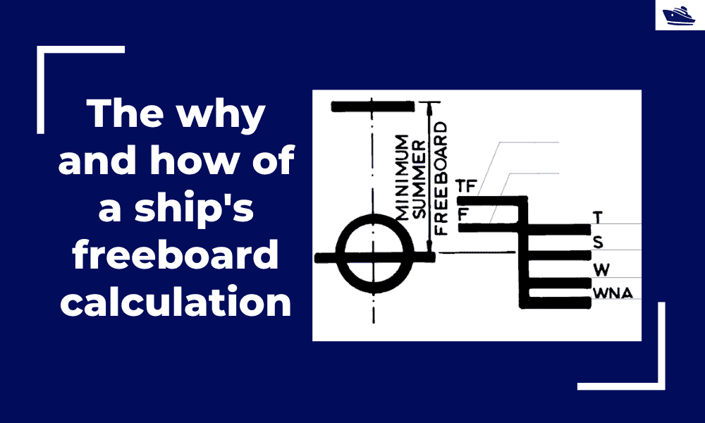
The why and how of freeboard calculation of a ship
Introduction Freeboard is a common term used in vessel operations. Freeboard is the smallest vertical distance between the waterline and the freeboard deck (generally the upper deck) along the length of the vessel. The term ‘smallest’ is of significance, as the height...
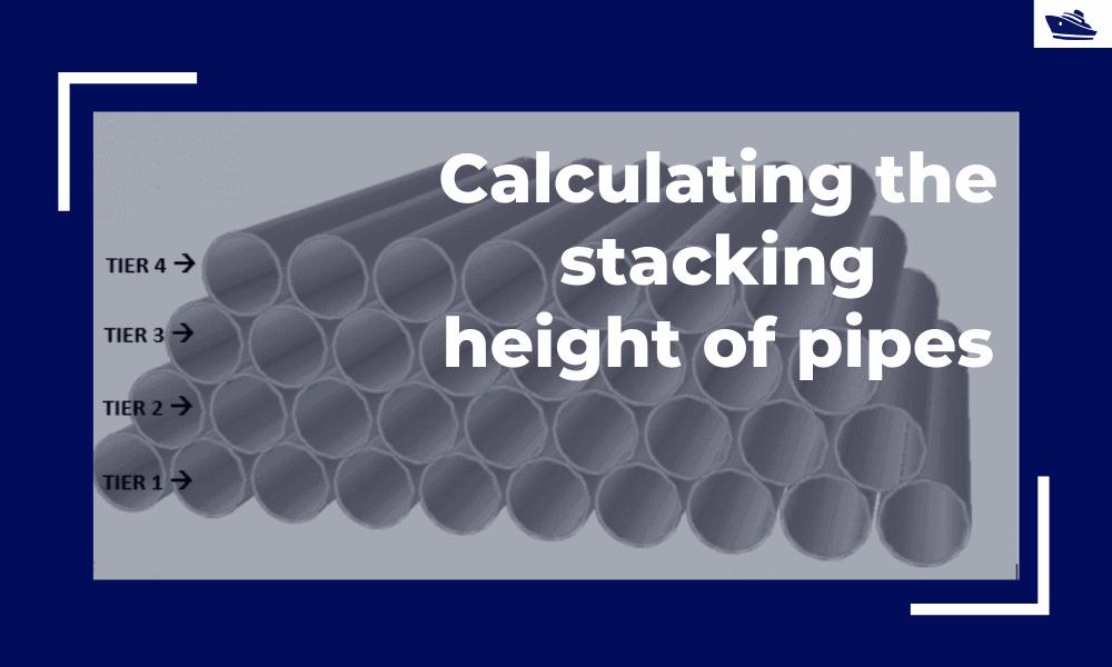
Calculating the maximum stacking height of pipes
Introduction Pipes (or linepipes or joints) are used for multiple purposes and locations in the maritime/offshore industry. Onshore and offshore pipelines are used for transportation of fluids on land, over and underwater. Pipes are fabricated in an onshore facility...
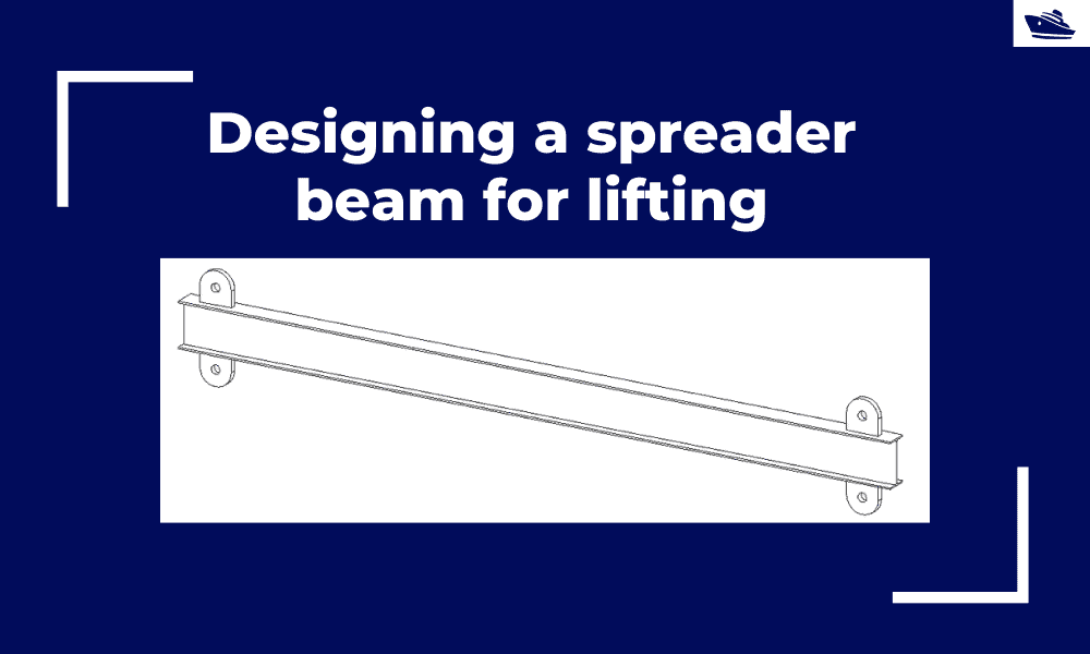
Designing a spreader beam for lifting
Spreader beams are universally applied gear which is widely used in various types of lifting operations, onshore and offshore. In this article, we will explore the design of a basic spreader beam and see what design checks are needed to establish the suitability of a...
Safe Towing: Calculating a towline’s catenary and sag
Introduction Towlines connect a tug to the vessel being towed and are defined by multiple characteristics like Weight, Diameter, and Stiffness. The tension in the towline during the towing operation is not static but keeps varying with the distance between the tug and...
Designing the lashings of deck cargo using IMO CSS
Introduction More than 70% of the earth is covered by water, which makes shipping historically the easiest and cheapest way of connecting manufactures and customers across the globe and can be reasonably considered to be the artery of the global economy....

I would like to ask you if it is possible to send me the 2nd Part of the article ”The bulbous bow – why some ships have it and others don’t”.
Hi George
It’s on the way. Will update by mid-April 2020
Hi George
Apologies for the delay in posting the Part 2. You can access it here:
https://thenavalarch.com/the-bulbous-bow-types-characteristics-and-effects/
Student
How do we access the articles?
Hi Nick, you just need to create a free account