Introduction
Bolts are very commonly used fastening items and used in a variety of configurations. In this article, we will explore in-depth the design of a bolt used in connecting two members at a joint (bolted joint). We’ll see what properties of the bolt are important for its sizing, look into the forces the bolt will experience, and also evaluate the stresses which it will experience.
The guidelines/regulations followed for this article are based on Eurocode3.
Bolted Joint
A bolted joint comprises an incoming member welded to an endplate. The endplate has got bolt holes for connection to another member. We can see this in Figure 1 below.
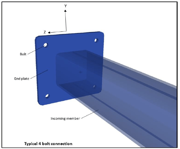
Figure 1 – Typical joint connection
Forces on the bolted joint
Any joint will experience the six degrees of freedom – three translations and three rotations. The three translatory movements will result in forces, while the three rotatory movements will result in moments.
Looking at the figure above, we can see that the forces and moments are as below:
- Axial Force in X-direction
- Shear Force in Y-direction
- Sheer Force in Z-direction
- Moment about X-axis
- Moment about Y-axis
- Moment about Z-axis
The above six forces/moments should be known to the user before commencing the bolt’s design.
Material Properties of endplate and bolts
The material properties of the endplate and the bolts are the starting inputs for the calculations. For the plate, the yield strength, tensile strength, and material factors are needed.
For the bolts, the bolt grade needs to be selected first. The bolt grades specified in Eurocode 3 are A1, A2, A4, 4.6, 4.8, 5.6, 5.8, 6.8, 8.8, and 10.9. The material properties (yield and tensile strength) will depend on the bolt grade. The material factor for the bolts is user input.
Bolt Geometry
The geometry of bolts depends on the class of bolt selected. Different classes of the bolt as per the Eurocode 3 are: M10, M12, M16, M20, M24, M27, M30, and M36. Each of them is characterized by the following properties: bolt diameter, bolt hole diameter, and bolt area.
Plate Geometry
The plate geometry is characterized by the following:
- Endplate thickness tp
- End distances between plate edge and bolt e1 & e2
- Spacings between the bolts in the y and z directions p1 & p2
Figure 2 below illustrated the plate geometry inputs
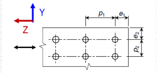
Figure 2 Plate Geometry Inputs
Geometry Checks
The spacing of bolts, the end distances from the plate, etc. are subject to some minimum requirements. These are shown below.
p1,p2,e1,e2 are the distances as shown in figure 2, and d0 is the bolt hole diameter, while tp is the plate thickness
With the inputs and geometry check in place, stress assessments of the bolts is the next step.
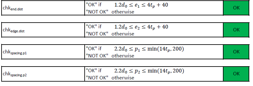
Figure 3 Bolt Geometry Checks
Forces and moments
The total forces and moments on the joint are taken by the total number of bolts. The forces and moments on a bolt can be calculated from the forces and moments on the joints. For example, the tensile force on the bolts can be found by dividing the total axial force by the number of bolts, and adding to it the axial forces arising from the moments in the Y and Z directions (by dividing the moments by the lever arm of the moment). Similarly, the shear force can be found out as the resultant of the joint forces in Y and Z directions and adding to it the shear force arising due to the moment in the axial direction.
Design resistances and capacity checks
The checks for an individual bolt can be performed by calculating the design resistances of a bolt. These include the following and are derived from the material and geometrical properties of the bolt
- Shear resistance
- Tension resistance
- Bearing resistance
- Punching shear resistance
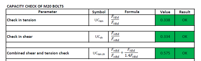
Following the above, the checks for the bolt’s design are performed to calculate the different unity checks as listed below.
- Check in tension
- Check in shear
- Combined shear and tension check
- Bearing Resistance Check
- For end bolts
- For inner bolts
- Punching Shear check
Each of the above checks should result in a UC value of less than 1.0 for the bolt.
That completes this article on designing bolts for joint connections. Please do check out TheNavalArch’s own app on bolt design, and let us know in the comments section if you have any queries.
Disclaimer: This post is not meant to be authoritative writing on the topic presented. thenavalarch bears no responsibility for the accuracy of this article, or for any incidents/losses arising due to the use of the information in this article in any operation. It is recommended to seek professional advice before executing any activity which draws on information mentioned in this post. All the figures, drawings, and pictures are property of thenavalarch except where indicated, and may not be copied or distributed without permission.
FLOATING WIND TURBINES -TRANSPORTATION AND INSTALLATION ENGINEERING
By Alan Crowle, BSc, MSc, CEng, CMarEng, FRINA, FMAREST, FSCMS Masters by Researcher, University of Exeter, College of Engineering, Mathematics and Physical Sciences, Renewable Energy Group Summary Floating offshore wind turbines are an emerging source of marine...
Preparation for Dry-docking of an oil tanker: A Chief Engineer’s approach
Introduction Dry-docking of a vessel is required at every 5 yearly intervals to carry out inspection of hull, propeller and other components which are normally submersed in water all the time. This is a requirement by ship’s classification societies. However, some...
Using simple tools for efficient Passage Planning for seagoing vessels
Introduction Planning a vessel’s voyage is a critical detailed exercise, and the main goal is to ensure safe and efficient passage between two ports. The Master has the responsibility for the vessel voyage planning, but very often he delegates the actual voyage...
Designing a closed chock as per IACS rules
Introduction Chocks are used universally for mooring and towing operations on ships. For towing operations, Chocks are used for guiding the towing rope from the winch through the outer shell of the vessel to the tug. For mooring operations, the chock is used to...
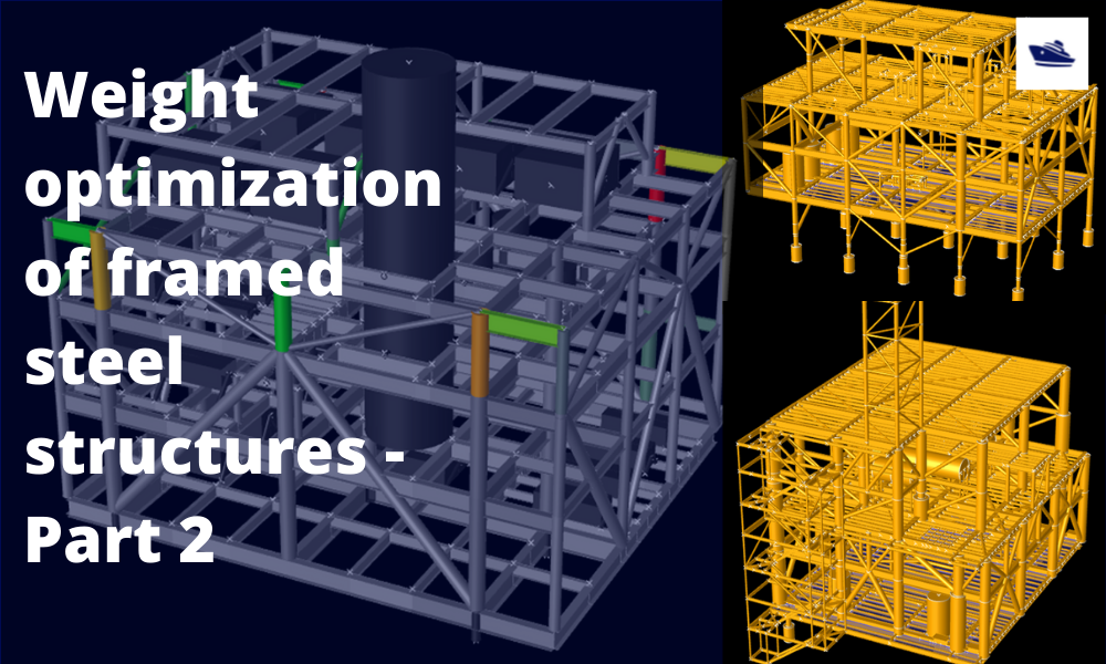
The Optim22 method of hull optimization – Part 2
This is a follow-up article to the previous article on Framed Structures Optimization. 1.1 Abstract A previous article introduced the Optim22 method. This one adds additional background information plus 3 more case studies to...
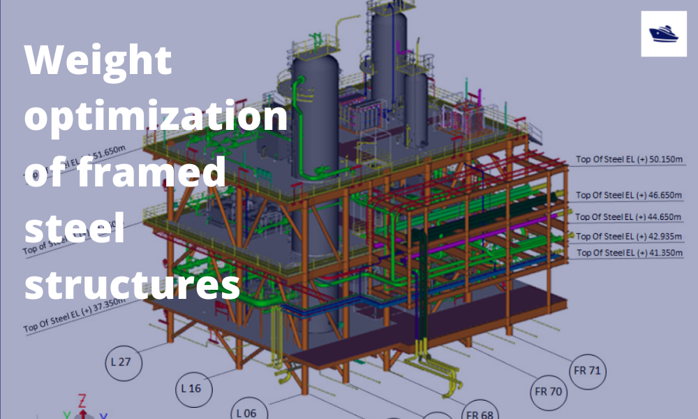
The Optim22 Method of Weight Optimization of Framed Steel Structures
1 Abstract A semi-automated structural weight optimization system is presented for framed structures of post and beam construction which is based on basic structural member design principles. The approach is to adjust member properties in a manner that...

Combating rising seas with floating structures
Introduction Rising sea level is an existential threat for many coastal cities. The sea is rising subtly but relentlessly at an exponential rate. Many predictions of how high and how fast it will rise in the next 50 years have proved to be understated. According to...
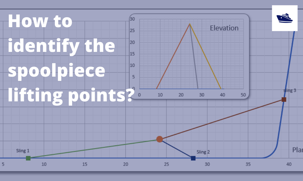
How to identify the spoolpiece lifting points?
In the offshore construction industry, the connection between the newly installed pipeline and the riser is accomplished via a series of ‘spoolpieces’ (or spools). The spool is fabricated by welding pipe joints to form an L-shaped, Z-shaped, or possibly a straight...
The importance of clear decision support before marine operations
Our oceans are interspersed with human activities: be it fishing, marine transportation, or offshore operations. These operations usually involve assets worth multiple million dollars, be it the produce or the equipment or in most cases, the human life. Produce from...
Sea Pressure Loads Calculation based on DNV Rules
Introduction Sea pressure loads are an important factor in the structural design of a vessel. What is sea pressure load? As the term suggests, it is the external pressure on the vessel due to the surrounding sea. What kind of pressure it is, and how to...

N/A